TB-9-2320-279-13-P-2 - Page 406 of 460
II
106700-7
Rev. -
r.
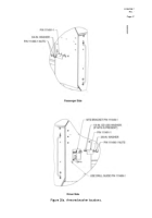
Insert bolt (1/4 – 20 x 1-3/4 LG) and washers (111403-1, 1/4, GR8, SAE) into the
5/16-in. drilled hole (see Figure 28a) and secure with locknut (1/4 – 20) inside the
cab.
Torque the fastener to 9 ft-lb.
s.
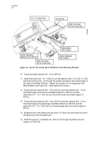
If the MTS Bracket (P/N 111449-1) has been installed on the driver’s side,
two washers (1/4 x 1.0 OD, USS) will be required to be used as spacers to install the
rectangular armor washer (P/N 111491-1).
If the MTS Bracket is not installed, the
two spacer washers are not required (see Figure 28a).
t.
Place two spacer washers (1/4 x 1.0 OD, USS) onto the studs protruding from the rear
armor panel (Note:
Use spacer washers only if the MTS Bracket is installed) (see
Figure 28a).
u.
Place the rectangular armor washer (P/N 111491-1) onto the stud and apply Loctite
to the stud threads.
Secure the rectangular armor washer with two washers
(3/8, GR8, SAE) and two nuts (P/N 111490-1).
Torque nuts to 4 ft-lb.
v.
Repeat Steps “a” through “u” for the passenger-side Rear Cab Armor Panel
(P/N 106724-4), except only one armored washer installation is required
(see Figure 26a and 28a) and only one 1/4-in. hole is required to be drilled.
5.1.6
Install the Blast Deflectors, Kit P/N 106706-3 (see Figure 29)
NOTE
HEMTT Armor Kits manufactured after 2004 may include additional mine blast
components (Mine Blast Shield, P/N 111458-1, and Radius Block, P/N 111493-1).
All assembly instructions are the same for kits with or without the additional components,
except as noted in Section 5.1.6, Item c, Step 9.
a.
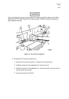
Install the Driver’s-side (LH) Blast Deflector.
1.
Remove the drag link from the pitman arm on the steering box to gain access to
the fender supports.
Back to Top


