TB-9-2320-280-35-13 - Page 54 of 148
5-26
TB 9-2320-280-35-13
12-9.
Install locking base (17) to isolation mount top plate (6) with two included screws (16) and
Loctite No. 271.
12-10.
Install lanyard (19) on locking base (17) with included screw (18), lockwasher (20), and
Loctite No. 271.
12-11.
Install lanyard (19) on locking bar (23) with included screw (21) and lockwasher (22).
12-12.
Attach isolation mount top plate (6) to isolation mount bottom plate (7) with four screws (24) and
four lockwashers (25). Position locking bar (23) on locking base (17).
6
17
16
18
20
19
17
~
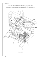
Figure 5-38.
Figure 5-39.
21
22
19
23
Figure 5-40.
17. LOCKING BASE – 12018-1907-01 – QTY. 1
19. LANYARD – Z33-0002-306 – QTY. 1
23. LOCKING BAR – 12018-1908-01 – QTY. 1
Back to Top


