TB-9-2320-280-35-14 - Page 112 of 148
5-90
TB 9-2320-280-35-14
Section XXXI.
HF 150 WATT RADIO MOUNT INSTALLATION (FOUR-MAN VEHICLES)
NOTE
Perform the following procedures for four-man vehicle
configuration only.
31-1.
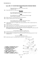
Position R/T mount (4) on vehicle floor (5).
WARNING
Do not drill through fuel tank. Damage to equipment or injury or
death to personnel may result.
NOTE
Do not drill directly over support beam. There will not be enough
space for insert to sit properly.
31-2.
Remove capscrew (1) and lockwasher (2) from radio mount (3).
31-3.
Separate resilient mount (4) from radio mount (3).
NOTE
Locate resilient mount on vehicle floor with inserts located on
second and fourth rib from rear seat on left side.
31-4.
Using resilient mount (4) as template, locate, mark, and drill four 0.390 in. diameter holes (6) in
vehicle floor (5).
31-5.
Install four inserts (7) in vehicle floor (5).
31-6.
Install resilient mount (4) on vehicle floor (5) with four capscrews (9) and four lockwashers (8).
31-7.
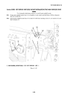
Remove two clamps (11), screws (10), washers (13), four nuts (14), and two metal
blocks (12) from radio mount (3). Save two clamps (11), screws (10), washers (10), and four nuts (14)
for installation; discard two metal blocks (12).
NOTE
Use Loctite 242 or equivalent on existing screws.
31-8.
Install locking bar (16) on radio mount (3) with four existing screws (15).
31-9.
Install lanyard (20) on locking bar (16) and theft deterrent (19) with existing capscrews (17) and
lockwashers (18).
NOTE
Use Loctite 242 or equivalent on screw.
31-10.
Install radio mount (3) on resilient mount (4) with screw (1) and lockwasher (2).
1
2
3
4
5
6
7
8
9
~
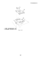
Figure 5-110.
1. CAPSCREW – B1821BH025C062N – QTY. 4
2. LOCKWASHER – MS35338-44 – QTY. 4
3. R/T RADIO MOUNT (TOP HALF) –
P/O RF-5073VSM – QTY. 1
4. R/T MOUNT – RF-5073VSM – QTY. 1
7. INSERT – 12446871-2 – QTY. 4
8. LOCKWASHER – MS45904-71 – QTY. 4
9. CAPSCREW – B1821BH025C100N – QTY. 4
Back to Top


