TB-9-2320-302-13-P-1 - Page 283 of 380
Installation Manual – P/N 0257550622-00
(Doc No.:
II
113500-1 D)
Freightliner M915 / M916 -
Crew Protection Kit
Page 91 of 125
5.21
LH Door Accessories Assembly
5.21.1
Parts, Fasteners, Special Tools, and Materials
Parts
Part No.
Alternate
Part No.
Description
Find No. in
Procedure
Quantity
NA
NA
Fasteners:
Find No.
(Table 3-5)
Part No.
Description
Size
Quantity
53*
Bolt, HEX, NC
1/4" x 1/2"
3
Special Tools/ Materials
Description:
Vendor/Part-Number:
None
*Fasteners are supplied as part of 0257040001-00.
5.21.2
Installation Instructions
1.
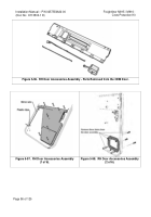
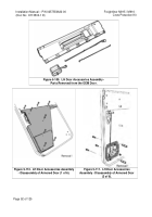
From the OEM door, remove the external door handle, the internal door handle with its
housing and linkage, and the interior lock button with linkage.
These items are illustrated
in Figure 5-109.
Remove the wiper strip from the top edge of the OEM door handle
assembly.
2.
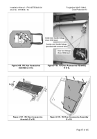
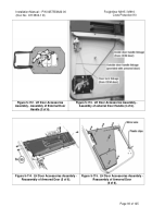
Remove the interior cover from the armored door as shown in Figure 5-110.
3.
Remove the external door handle adaptor plate from the armored door as shown in
Figure 5-111.
4.
Route mirror wire under the internal door cover plate as shown in Figure 5-115.
Secure the
wire to the door with plastic clips (P/N 53000028-00) near the forward edge.
5.
Assemble the OEM external door handle into the door handle adaptor plate as shown in
Figure 5-112.
6.
Connect linkages as illustrated in 5-113.
Operate the internal and external handles as well
as the lock button to ensure that all items function correctly.
Close the door to verify
proper operation of the latch mechanism.
Adjust the position of the latch and the striker
post as necessary.
7.
Reinstall the components on the door as shown in Figures 5-114 and 5-115 using the
hardware removed from the armored door.
Back to Top

