TB-9-2320-302-13-P-2 - Page 284 of 396
ArmorWorks
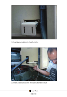
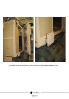
2.) Pictured above is the Manifold assembly that was unbolted from the original angle
bracket. Position it on the side of the box as shown, align drill with ¼” holes, and mount
it to the box with the original bolts.
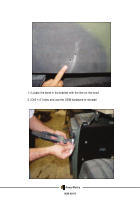
3)
Next, position the angle bracket with the electrical connectors on the box as shown,
align drill with ¼” holes, and bolt to the box with spares hardware.
0038 00-72
Back to Top


