TB-9-2320-335-13-P - Page 490 of 680
TB 9-2320-335-13&P
D-2
Section II. ILLUSTRATED MANUFACTURING INSTRUCTIONS (Cont'd)
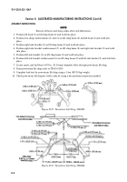
ASSEMBLY INSTRUCTIONS:
NOTE
Remove all burrs and sharp edges after each fabrication.
1. Position lift hook (3) on lift sling beam (2) and weld into place.
2. Position two sling reinforcements (1) and (4) on lift sling beam (2) and lift hook (3) and weld into
place.
3. Position right side bracket (8) on lift sling beam (2) and weld into place.
4. Position right side bracket reinforcement (7) on lift sling beam (2) and right side bracket (8) and weld
into place.
5. Position left side bracket (5) on lift sling beam (2) and weld into place.
6. Position left side bracket reinforcement (6) on lift sling beam (2) and left side bracket (5) and weld into
place.
7. Locate, mark, and drill four 0.437-in. (11.10-mm) diameter holes through powertrain lift sling.
8. Paint powertrain lift sling (refer to TM 43-0139).
9. Complete load test for powertrain lift sling using a 1-ton (907.18-kg) weight.
10. Check powertrain lift sling for weld cracks by using a dye penetrant inspection method.
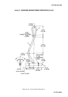
Figure D-73. Powertrain Lift Sling, 5992404.
Figure D-72. Powertrain Lift Sling, 5992403.
Back to Top


