TB-9-2320-387-35-4 - Page 97 of 109
5-81
TB 9-2320-387-35-4
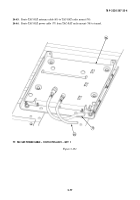
Figure 5-107.
105
103
100
101
102
104
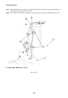
Figure 5-106.
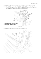
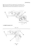
24-56.
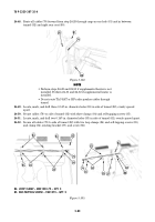
Route remaining cables to integrated rack (99) using one loop clamp (101), existing
capscrew (104), lockwasher (103), and washer (102).
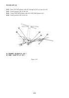
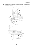
24-57.
Route cables along bar (105) to top of integrated rack (99) with two tiedown straps (100).
100. TIEDOWN STRAP – MS53367-1-0 – QTY. 2
101. LOOP CLAMP – MS21333-104 – QTY. 1
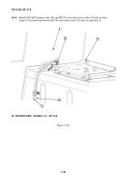
NOTE
Remove terminal board cover before connecting leads, and
reinstall cover after leads are connected.
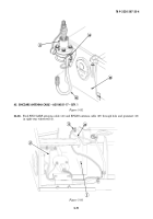
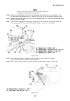
24-53.
Attach heat shrink tubing (90) and two terminal lugs (88) and (95) to power cable negative lead
(94) and power cable positive lead (91). (Refer to TM 9-2320-387-24 for terminal connector repair.)
24-54.
Connect power cable positive lead (91) to 24-volt terminal board (97), located on cab enclosure panel
(98), with existing nut (89).
24-55.
Connect power cable negative lead (94) to ground strap (96), located on cab enclosure panel (98),
with existing nut (93). Secure leads (91) and (94) together with tiedown strap (92).
88
89
90
91
98
92
93
94
90
95
96
97
~
88. TERMINAL LUG – 7728780 – QTY. 1
90. SHRINK TUBING – MS23053/4-302-0 – QTY. A/R
92. TIEDOWN STRAP – MS3367-1-0 – QTY. A/R
95. TERMINAL LUG – 7728777 – QTY. 1
99
Back to Top

