TB-9-3950-253-13-P
PALLETIZED LOAD SYSTEM TRUCK, M1075 and M1075A1 (PLS) AND HEAVY EXPANDED MOBILITY TACTICAL TRUCK, M1120, M1120A2, AND M1120A4 (HEMTT), ENHANCED CONTAINER HANDLING UNIT (E-CHU)
TECHNICAL BULLETIN; OPERATOR AND FIELD MAINTENANCE, INSTALLATION INSTRUCTIONS, AND REPAIR PARTS AND SPECIAL TOOLS LIST
JULY 2009
TB-9-3950-253-13-P - Page 181 of 704
TB 9-3950-253-13&P
0019-1
Change 1
0019
FIELD MAINTENANCE
-
FIELD MAINTENANCE TROUBLESHOOTING PROCEDURES
MALFUNCTION
TEST OR INSPECTION
CORRECTIVE ACTION
0.
ELECTRICAL SYSTEM
NOTE
• Tag all wires, connections, hoses and fittings upon removal.
• Cap all hoses and fittings to prevent contamination.
• Install all wires, connections, hoses, and fittings as tagged during removal.
1. NO STOWAGE FUNCTION (ERROR CODES 0 AND 1).
Step 1.
Check vehicle charging system for correct operation (PLS: TM 9-2320-364-14&P, HEMTT: TM
9-2320-326-14&P).
Step 2.
Check for shorted sensor.
a.
Set ignition switch and battery disconnect switch to OFF position (PLS: TM 9-2320-364-
14&P, HEMTT: TM 9-2320-326-14&P).
b.
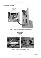
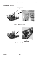
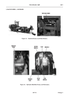
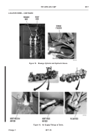
Disconnect wiring harnesses from middle frame sensor, hook arm sensor, stowage angle
sensor, and two stowage guide sensors (WP 0034).
NOTE
When ignition switch is turned on after battery disconnect switch has been turned off and
back on, error codes 1 and 24 may alternately display for one minute. This error code
indicates that temporary settings were lost while battery disconnect switch was off, and is
consistent with normal operation.
c.
Set battery disconnect switch and ignition switch to ON position (PLS: TM 9-2320-364-
14&P, HEMTT: TM 9-2320-326-14&P).
d.
If error code 0 or 1 is still displayed, proceed to Step 3.
e.
If error code 0 or 1 is not displayed, reconnect sensors one at time to identify faulty sensor.
1. Set ignition switch and battery disconnect switch to OFF position.
2. Connect right side stowage guide sensor harness to right side stowage guide sensor
(WP 0034).
3. Set battery disconnect switch and ignition switch to ON position.
4. If error code is displayed, replace right side stowage guide sensor (WP 0034).
5. If no error code, proceed with this sequence.
6. Set ignition switch and battery disconnect switch to OFF position.
7. Connect left side stowage guide sensor harness to left side stowage guide sensor (WP
0034).
8. Set battery disconnect switch and ignition switch to ON position.
36
Back to Top

