TM-10-4930-247-13-P - Page 111 of 309
TM 10-4930-247-13&P
4-14.
NON-VALVED DRY BREAK COUPLING REPAIR.
This task consists of:
a.
Disassembly
b.
Cleaning
c.
Inspection
d.
Repair
e.
Assembly
INITIAL SET-UP
Tools:
Material/Parts:
General Mechanics Tool Kit (App B, Sect III, Item 1)
Silicone Compound (Item 3, App F)
Equipment Condition:
Cleaning Solvent (Item 1, App F)
Component removed from fuel system (para 3-4a)
Wiping Rag (Item 2, App F)
Bumper (1) (Item 1, App J)
Repair Kit (Item 4, App J)
a.
Disassembly.
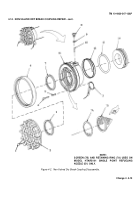
Refer to figure 4-2.
NOTE
Ensure that all parts identified as mandatory replacement parts are discarded and
replaced with new components.
(1)
Disconnect dust cap (2) from body (11).
(2)
Remove seal (1) from dust cap (2).
(3)
Disconnect wire ring (3) from end of retainer pin (4).
(4)
Remove retainer pin (4) and spring (5) from body (11).
(5)
Remove bumper (6) from body (11).
(6)
Remove seal (7) from body (11).
(6A)
(Model HTARS101 Single Point Refueling Nozzle) Remove retaining ring (7A) and screen (7B) from body
(11).
(7)
Remove screw (8) and attached preformed packing (9) from body (11).
NOTE
To prevent loss of balls and aid assembly, place a suitable container under body
opening.
Catch all balls as they fall from body.
(8)
Position body (11) so that opening for balls (10) is pointing down.
(9)
Rotate body (11) back and forth on fitting (11) until 41 balls (10) are removed.
(10)
Remove body (11) and spring (12) from fitting (14).
(11)
Remove preformed packing (13) from fitting (14).
4-12
Change 4
Back to Top


