TM-3-1040-279-12-P - Page 202 of 389
TM 3-1040-279-12&P
4-30
FOG OIL PUMP ASSEMBLY.
This task covers replacement of:
a.
Strainer Assembly
(P. 4-134)
e.
Quick Disconnect Coupling
(P. 4-139)
b.
Pressure Relief Valve
(P. 4-136)
f.
Cable Assembly 6J3
(P. 4-140)
c.
Hose Assembly
(P. 4-137)
g.
Fog Oil Pump
(P. 4-142)
d.
Hose Assembly
(P. 4-138)
INITIAL SETUP
Tools
General Mechanic’s Automotive Tool Kit
SC 5180-90-CL-N26
General Safety Instructions
Before performing any maintenance instructions
be sure circuit breaker CB1 is in OFF position.
Fog oil is very slippery. Clean up all spills
immediately to prevent injury to personnel.
a.
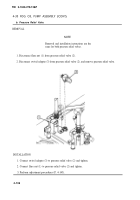
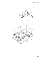
Strainer Assembly.
REMOVAL
NOTE
Removal and installation procedures are the same for both strainer
assemblies.
1.
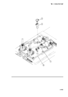
Disconnect fog oil hose (1) from elbow (2).
2.
Remove elbow (2) from strainer assembly (3).
3.
Remove strainer assembly (3) from fog oil pump assembly (4).
NOTE
If pipe nipple is removed with strainer assembly, remove nipple and install on
new strainer assembly.
INSTALLATION
1.
Installation strainer assembly (3) on fog oil pump assembly (4).
2.
Install elbow (2) on strainer assembly (3).
3.
Install fog oil hose (1) on elbow (2).
4-134
Back to Top

