TM-3-1040-279-12-P - Page 264 of 389
TM 3-1040-279-12&P
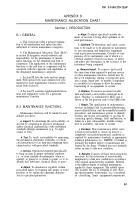
H . . . . . . General Support Maintenance
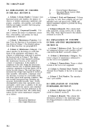
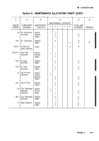
B-3 EXPLANATION OF COLUMNS
IN THE MAC, SECTION Il.
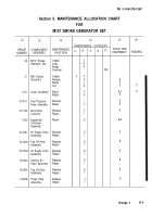
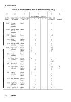
a. Column 1, Group Number.
Column 1 lists
functional group code numbers, the purpose of
which is to identify maintenance significant com-
ponents, assemblies, subassemblies, and modules
with the next higher assembly. End item group
number shall be “00”.
b. Column 2, Component/Assembly.
Col-
umn 2 contains the names of components, assem-
blies, subassemblies, and modules for which
maintenance is authorized.
c. Column 3, Maintenance Function.
Col-
umn 3 lists the functions to be performed on the
item listed in Column 2. (For detailed explana-
tion of these functions, see paragraph B-2).
d. Column 4, Maintenance Category.
Col-
umn 4 specifies, by the listing of a work time
figure in the appropriate subcolumn(s), the
category of maintenance authorized to perform
the function listed in Column 3. This figure
represents the active time required to perform
that maintenance function at the indicated
category of maintenance. If the number or
complexity of the tasks within the listed main-
tenance function vary at different maintenance
categories, appropriate work time figures will be
shown for each category. The work time figure
represents the average time required to restore an
item (assembly, subassembly, component, mod-
ule, end item, or system) to a serviceable condi-
tion under typical field operating conditions. This
time includes preparation time (including any
necessary disassembly/assembly time), trouble-
shooting/fault location time, and quality assur-
ante/quality control time in addition to the time
required to perform the specific tasks identified
for the maintenance functions authorized in the
maintenance allocation chart. The symbol desig-
nations for the various maintenance categories
are as follows:
C . . . . . . . . . . . Operator or crew
O . . . . . . . . .Organizational Maintenance
F. . . . . . . . . . .Direct Support Maintenance
L . . . . . . .Specialized-Repair Activity (SRA)
D . . . . . . . Depot Maintenance
e. Column 5, Tools and Equipment.
Column
5 specifies, by code, those common tool sets (not
individual tools) and special tools, TMDE, and
support equipment required to perform the desig-
nated function.
f. Column 6, Remarks.
This column shall,
when applicable, contain a letter code, in alpha-
betic order, which shall be keyed to the remarks
contained in section IV.
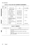
B-4 EXPLANATION
IN TOOL AND TEST
SECTION Ill.
OF COLUMNS
REQUIREMENTS,
a. Column 7, Reference Code.
The tool and
test equipment reference code correlates with a
code used in the MAC, section II, column 5.
b. Column 2, Maintenance Category.
The
lowest category of maintenance authorized to
use the tool or test equipment.
c. Column 3, Nomenclature.
Name or identi-
fication of the tool or test equipment.
d. Column 4, National Stock Number.
The
National Stock Number of the tool or test equip-
ment.
e. Column 5, Tool Number.
The manufac-
turer’s part number.
B-5 EXPLANATION OF COLUMNS
IN REMARKS, SECTION IV.
a. Column 1, Reference Code.
The code re-
corded in column 6, section II.
b. Column 2, Remarks.
This column lists
information pertinent to the maintenance func-
tion being performed as indicated in the MAC,
section II.
B-2
Back to Top

