TM-3-1040-279-12-P - Page 371 of 389
Subject
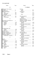
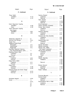
INDEX
Page
Subject
Page
A
C - Continued
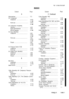
Abbreviations .
......................................
Air Compressor
Installation
.....................................
Removal.
........................................
Air Compressor Assembly
Painting .
.........................................
Removal/Installation.
. ....................
Wiring Diagram.
. ............................
Air Hose Assembly
Installation .
....................................
F-5
4-154,
4-168
4-154,
4-168
4-20
4-20
4-166
Removal.
........................................
Repair .
...........................................
4-83,
4-162,
4-164
4-83,
4-162,
4-164
4-90,
4-169,
4-170
Air Pressure Switch S106
Installation
.....................................
Removal.
........................................
Air Supply Hose Assembly
Installation
.....................................
Removal.
. .......................................
Repair.
. ..........................................
B
4-100
4-100
4-86
4-86
4-92
Cable Assembly W12
Installation.
. ....................................
Removal .
... .....................................
Cable Assemblies W13, W15, and W16
Installation.
. ....................................
Removal .
........................................
Cable Assembly 2J1
Installation.
. ....................................
Removal .
........................................
Cable Assembly 5J1
Installation .
.....................................
Removal .
........................................
Cable Assembly 5J2
Installation .
.....................................
Removal.
. .......................................
Cable Assembly 6J3
Installation .
....................................
Removal .
........................................
Capacitor Assembly
Installation.
. ....................................
Removal .
........................................
Check Air Compressor Pressure
Switch.
. ..............................................
Check Valve
Installation.
. ....................................
Removal .
........................................
Ball Valve
Installation .
....................................
Removal .
........................................
Blank Forms.
. .......................................
C
4-178
4-178
A-1
Checking Unpacked Equipment.
.........
Circuit Breaker CB1
Installation .
.....................................
Removal.
. .......................................
Common Table of Allowances.
............
Common Tools and Equipment.
. .........
Control Panel Assembly
Installation.
. ....................................
Painting.
. ........................................
Removal/Installation .
.....................
Removal .
........................................
Wiring Diagram .
.............................
Control Valve
Installation.
. ....................................
Removal.
. .......................................
Air Compressor Assembly.
. .................
Control Panel Assembly .
.....................
Smoke Generator.
................................
Corrosion Prevention and Control
(CPC) .
...............................................
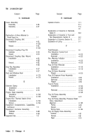
TM 3-1040-279-12&P
Cable Assembly (Air Compressor Pressure
Switch)
Installation .
....................................
4-163
Removal. . . . . . . . . . . . . . . . . . . . . . . . . . . . .
4-163
Cable Assembly (CU-1, Fire Detection Control
Unit)
Installation . . . . . . . . . . . . . . . . . . . . . . . . . . . . . . .
4-126
Removal . . . . . . . . . . . . . . . . . . . . . . . . . . . . . . . .
4-126
Cable Assemblies (1J1 thru 5J1)
Installation . . . . . . . . . . . . . . . . . . . . . . . . . . . .
4-116
Removal. . . . . . . . . . . . . . . . . . . . . . . . . . .
4-116
4-28
4-28
4-98
4-98
4-161
4-161
4-44
4-44
4-79
4-79
4-140
4-140
4-159
4-159
4-167
4-26,
4-165
4-26,
4-165
4-1
4-113
4-113
A-1
4-1
4-110
4-20
4-20
4-110
4-127
4-159
4-159
2-4
2-3
2-4
1-1
Change 4
Index 1
Back to Top

