TM-3-1040-279-12-P - Page 375 of 389
Subject
Page
Subject
Page
P - Continued
S - Continued
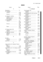
Purge Switch
Installation . . . . . . . . . . . . . . . . . . . . . . . . . . . . . . . . .
Removal
. . . . . . . . . . . . . . . . . . . . . . . . . . . .
Q
Quick Disconnect Coupling
Installation . . . . . . . . . . . . . . . . . . . . . . . . . . . . . . . . . .
Removal
. . . . . . . . . . . . . . . . . . . . . . . . . . . . . . . .
Quick Disconnect Coupling
(Gas Supply)
Installation . . . . . . . . . . . . . . . . . . . . . . . . . . . . . . . .
Removal. . . . . . . . . . . . . . . . . . . . . . . . . . . . . . . .
R
References (Appendix A) .
...................
Removal From Storage .
......................
Repair Parts.
. .......................................
Repairing Engine Head
Disassembly .
....................................
Inspect/Repair.
. .................................
Reassembly.
. ....................................
Reporting Equipment Improve-
ment Recommendations (EIR).
........
Replacing Engine Head
Installation .
....................................
Removal .
........................................
Relay K101
Installation
.....................................
Removal.
. .......................................
Relay K103 or K203
Installation
.....................................
Removal.
. .......................................
Relay K104
Installation .
....................................
Removal.
........................................
Retaining Straps and Anchor Straps
Installation .
....................................
Removal.
........................................
S
Schematic Diagram .
............................
Scope .
..................................................
4-115
4-115
4-139
4-139
4-58
4-58
A-1
4-191
4-1
3-10
3-10
3-12
1-1
3-9
3-8
4-78
4-78
4-111
4-111
4-156
4-156
4-174
4-174
4-187
1-1,
4-191,
C-1,
D-1,
E-1
TM 3-1040-279-12&P
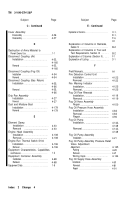
Sensing Element
Installation.
. ....................................
Removal.
. .......................................
Sight Indicator
Installation.
. ....................................
Removal.
. .......................................
Smoke Generator.
. ...............................
Smoke Generator Schematic .
.............
Smoke Temp Indicator
Installation.
. ....................................
Removal .
........................................
Solenoid Assembly
Installation.
. ....................................
Removal.
. .......................................
Solenoid Inlet Tube Assembly
Installation.
. ....................................
Removal.
. .......................................
Solenoid Valve L101
Installation.
. ....................................
Removal.
. .......................................
Special Information .
.............................
Special Instructions.
. ............................
Special Tools, TMDE,
and Support Equipment .
...................
Start Air Hose Assembly
Installation.
. ....................................
Removal .
........................................
Repair .
...........................................
Storage .
................................................
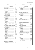
Strainer Assembly
Installation.
. ....................................
Removal . . . . . . . . . . . . . . . . . . . . . . . . . . . . . . . .
Strainer Element
Installation.
. ....................................
Removal.
.......................................
Supply Catalogs .
..................................
T
Technical Manuals.
..............................
Terminal Board
Installation .
.....................................
Removal.
. .......................................
Terminal Board TB11 or TB21
Installation.
. ....................................
Removal.
. .......................................
4-32
4-31
4-178
4-178
2-4
4-187
4-117
4-117
4-70
4-70
4-52
4-52
4-40
4-38
F-4
2-5
4-1
4-88
4-88
4-93
4-191
4-134,
4-146
4-134,
4-146
4-176
4-176
A-1
A-1
4-50
4-50
4-120
4-120
Change 4
Index 5
Back to Top

