TM-5-2330-378-14-P - Page 111 of 524
TM 5-2330-378-14&P
4-16. TROUBLESHOOTINGCHART(continued).
a.
LIGHTS (continued)
(5) TURN SIGNALS DO NOT WORK (M870) (continued).
CONTINUED
FROM STEP B
C.
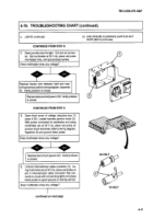
Remove light body from semitrailer (para 4-32).
Cut brown orwhite wire from red lead wire (refer
to wiring diagram, Appendix K). Using multim-
eter set at 30 V dc, place red probe on brown or
white wire and ground black probe while assis-
tant applies brakes.
Does multimeter
show any voltage?
-A
-..db.-
I
_@q
_Iqw@
_411110,
Replace light assembly (para 4-32).
Verify
problem is solved.
D.
Remove
voltage
reduction box cover (pare
4-35). Connect intervehicular
cable to terminal.
With multimeter
set at 30 V dc, place red probe
on terminal for white or brown harness wire on
junction
box, and ground black probe while as-
sistant applies brakes.
Does multimeter show any voltage?
-ddk.-
r
Replace brown orwhitewirefrom
voltage reduction
ep
ce
ft or ri
'
box to left or right turn signal (para 4-34). Verify
ox 0 1
is solv
g
prob'tlaem is solved.
E. Unhook intervehicular cable connector (1). Us-
ing multimeter
set at 30 V dc, place red probe on
two pins for turn signals and ground black probe
on towing vehicle while assistant applies brakes.
ri
Does multimeter
show voltage on both pins?
I
continued
on
next
page
4-23
Back to Top


