TM-5-2350-262-20-1 - Page 476 of 776
TM 5-2350-262-20-1
Change 3
4-127
Note
Although the Bilge Pump is considered
Not Mission Essential and will no longer
be supported with spare and repair parts,
this task contains maintenance procedures
For Your Information Only.
See TB 43-
0001-62-7 (dated Oct 98) for Instructions
to Isolate and Disconnect a Non-
Functional Bilge Pump.
A
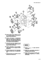
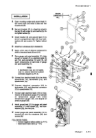
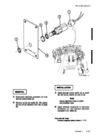
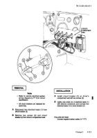
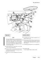
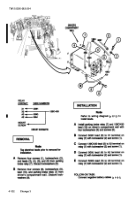
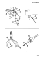
Remove two scews (1), lockwashers (2), and
washers (3) from bracket (4).
Remove bracket (4)
from driver’s compartment wall.
Discard
lockwashers (2).
B
Remove screw (5), lockwasher (6), and clamp (7)
from driver’s compartment wall.
Discard
lockwasher (6).
C
Disconnect leads (8) and (9) from leads (10) and
(11).
DISASSEMBLY
A
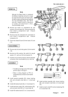
Remove clip (12) and roller guide (13) from switch
(14).
B
Remove nut (15), washer (16), switch (14), keyed
washer (17), and nut (18) from bracket (4).
C
If switch (14) is not to be reused, remove electrical
connectors from circuit leads (8), (9), and (19).
ASSEMBLY
Note
•
If installing new bilge pump “ON” switch,
perform steps A through F.
•
Refer to wiring diagram (p FP-3) to
install electrical connectors and marker
bands.
A
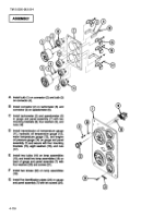
Install terminal assembly (20), sleeve bushing
(21), and connector shell (22) on 1 circuit lead
(11).
B
Install 450 marker band (23) on 1 circuit lead (11).
C
Install electrical contact (24), slotted washer (25),
and connector shell (26) on 3 circuit lead (9).
D
Install 450 marker band (27) on 3 circuit lead (9).
REMOVAL
E
Install terminal assembly (28), sleeve bushing
(29), and connector shell (30) on 2 circuit lead
(19)
F
Install connector shell (31) and end seal plug (32)
on 2 circuit lead (19).
Back to Top

