TM-5-2350-262-20-1 - Page 600 of 776
TM 5-2350-262-20-1
Change 3
4-244.1
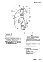
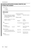
REMOVAL
Note
If replacing the resistor only perform step
D.
If replacing blower motor housing
perform steps A through I.
A
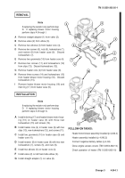
Remove straight adapter (1) from valve (2).
B
Remove valve (2) from elbow (3).
C
Remove two elbows (3) from heater core (4).
D
Remove two screws (5), nuts (6), lockwashers (7),
and resistor (8) from heater case (9).
Discard
lockwashers (7).
E
Remove two grommets (10) from heater core (4).
F
Remove two screws (11) and lockwashers (12)
from clips (13).
Discard lockwashers (12).
G
Remove heater core (4) from heater case (9).
H
Remove three screws (14) and lockwashers (15)
from heater blower motor housing (16).
Discard
lockwashers (15).
I
Remove heater blower motor housing (16) and
inlet ring (17) from heater case (9).
9
4
3
2
1
3
7
6
7
6
5
8
15
16
14
11
12
10
13
17
INSTALLATION
A
Install inlet ring (17) and heater blower motor hous-
ing (16) on heater case (9) with three new
lockwashers (15) and screws (14).
B
Install heater core (4) in heater case (9) with two
clips (13), new lockwashers (12), and screws (11).
C
Install two grommets (10) in heater case (9) and
heater core (4).
D
Install resistor (8) in heater case (9) with two new
lockwashers (7), screws (5), and nuts (6).
E
Install two elbows (3) on heater core (4).
F
Install valve (2) on left hand side elbow (3).
G
Install straight adapter (1) on valve (2).
FOLLOW-ON TASKS:
Heater motor blower assembly installed (p 4-242.4)
Heater assembly installed (p 4-242.2)
Connect negative battery cables (p 4-84)
Close engine access covers (TM 5-2350-262-10)
Check operation of heater (TM 5-2350-262-10)
Note
If replacing the resistor only perform step
D.
If replacing blower motor housing
perform steps A through G.
4
10
Back to Top

