TM-5-2350-262-24P - Page 5 of 567
TM 5--2350--262--24P
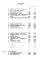
TABLE OF CONTENTS - (Continued)
Figure
WP Sequence
No
No
iii
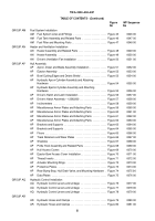
GROUP AM
Fuel System Installation
AM
Fuel System Lines and Fittings
Figure 45
0046 00
..........................
AM
Fuel Tank Assembly and Related Parts
Figure 46
0047 00
...................
AM
Fuel Filter and Mounting Parts
Figure 47
0048 00
...........................
GROUP AN
Heater and Ventilation Installation
AN
Heater Assembly and Related Parts
Figure 48
0049 00
......................
AN
Heater Assembly
Figure 49
0050 00
......................................
AN
Driver’s Ventilation Fan Installation
Figure 50
0051 00
.......................
GROUP AP
Hull Assembly
AP
Apron, Dozer and Blade Assembly Installation
Figure 51
0052 00
.............
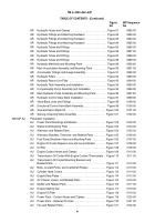
AP
Ejector Assembly
Figure 52
0053 00
......................................
AP
Bowl Cutting Edges and Debris Shield
Figure 53
0054 00
....................
AP
Hydraulic Apron Cylinder Assembly and Attaching
Hardware
Figure 54
0055 00
.............................................
AP
Hydraulic Ejector Cylinder Assembly and Attaching
Hardware
Figure 55
0056 00
.............................................
AP
Driver’s Hatch and Latch Installation
Figure 56
0057 00
......................
AP
Driver’s Hatch Assembly -- 12362200
Figure 57
0058 00
.....................
AP
Inclinometers
Figure 58
0059 00
..........................................
AP
Miscellaneous Armor Plates and Attaching Parts
Figure 59
0060 00
...........
AP
Miscellaneous Armor Plates and Attaching Parts
Figure 60
0061 00
...........
AP
Miscellaneous Armor Plates and Attaching Parts
Figure 61
0062 00
...........
AP
Miscellaneous Armor Plates and Attaching Parts
Figure 62
0063 00
...........
AP
Brackets and Supports
Figure 63
0064 00
.................................
AP
Brackets and Supports
Figure 64
0065 00
.................................
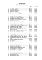
AP
Floors
Figure 65
0066 00
................................................
AP
Track Retainers and Wear Plates
Figure 66
0067 00
........................
AP
Shackles
Figure 67
0068 00
.............................................
AP
Pintle Hook Assembly and Related Parts
Figure 68
0069 00
..................
AP
Hull Access Covers
Figure 69
0070 00
....................................
AP
Ejector Bowl Access Cover Installation
Figure 70
0071 00
....................
AP
Thread Inserts
Figure 71
0072 00
.........................................
AP
Actuator Mounting Rings
Figure 72
0073 00
................................
AP
Protective Plates
Figure 73
0074 00
.......................................
AP
Rear Bump Stop, Hull Drain Valve, and Mounting Hardware
Figure 74
0075 00
.
AP
Data Plates
Figure 75
0076 00
...........................................
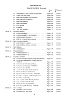
GROUP AQ
Hydraulic Control Installation
AQ
Hydraulic Control Levers and Linkage
Figure 76
0077 00
....................
AQ
Hydraulic Control Levers and Linkage
Figure 77
0078 00
....................
AQ
Hydraulic Control Levers and Linkage
Figure 78
0079 00
....................
GROUP AR
AR
Hydraulic Hoses and Clamps
Figure 79
0080 00
............................
AR
Hydraulic Hoses and Clamps
Figure 80
0081 00
............................
Back to Top

