TM-5-2350-378-23-P - Page 188 of 644
FRONT CORNER (LEFT OR RIGHT) RAISES IN UNSPRUNG, BUT NOT SPRUNG MODE - Continued
STEP
2.
Perform No. 1 actuator oil flow and hydraulic pressure test.
NOTE
Have suitable container ready to catch oil.
a.
Stop engine; relieve hydraulic pressure.
b.
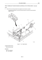
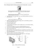
Disconnect No. 1 SPNSN UNIT- #9 hose (Figure 2, Item 2) at elbow (Figure 2, Item 6) on port 9
(Figure 2, Item 7) of No. 1 actuator (Figure 2, Item 4).
c.
Cap elbow (Figure 2, Item 6).
d.
Connect tee (Figure 2, Item 1), globe valve (Figure 2, Item 8), and pressure measuring device
(Figure 2, Item 3) to end of No. 1 SPNSN UNIT-#9 hose (Figure 2, Item 2).
e.
Connect a drain hose (Figure 2, Item 5) to open end of globe valve (Figure 2, Item 8).
f.
Place end of hose (Figure 2, Item 5) in container. Start engine. Open globe valve (Figure 2, Item 8).
g.
Observe for flow of oil.
CONDITION/INDICATION
Does oil flow freely?
DECISION
YES - Go to Step (3).
NO - Go to Step (10).
STEP
3.
Close globe valve and check hydraulic pressure.
Close globe valve (Figure 2, Item 8) and measure pressure on pressure measuring device
(Figure 2, Item 3).
CONDITION/INDICATION
Is hydraulic pressure greater than 2,500 psi (17,238 kPa)?
DECISION
YES - Go to Step (4).
NO - Go to Step (10).
STEP
4.
Check for blockage at port 9.
CONDITION/INDICATION
Is port 9 blocked?
DECISION
YES - Clear blockage. Remove all test equipment and connect hoses. Verify problem is solved.
NO - Go to Step (10).
TM 5-2350-378-23&P
0013
0013-4
Back to Top


