TM-5-2350-378-23-P - Page 220 of 644
HYDRAULIC OIL OVERHEATS - Continued
e.
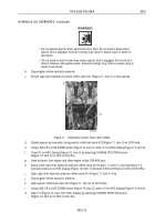
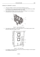
Loosen jam nut (Figure 15, Item 6) on main relief valve 13R (Figure 15, Item 1).
f.
For 13R (Figure 15, Item 1); have assistant simultaneously hold EJECTOR CONTROL lever in BACK
while holding right-hand SUSPENSION CONTROL lever in RAISE.
g.
Rotate adjusting screw (Figure 15, Item 5) on main relief valve 13R (Figure 15, Item 1) clockwise to
increase pressure or counterclockwise to decrease pressure.
T01323HDC
4
3
2
1
6
5
Figure 15.
Main Pump Relief Valves.
h.
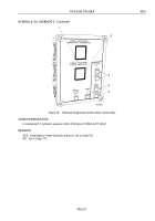
Once indication from transducer T-3 on HDC display (Figure 16, Item 1) hydraulic pressure is within
desired limits, tighten jam nut (Figure 15, Item 6).
T01324HDC
1
2
3
4
Figure 16.
HDC Control Valve.
i.
For 13L (Figure 15, Item 4); repeat previous steps for main relief valve 13L (Figure 15, Item 4) using left-
hand SUSPENSION CONTROL lever.
TM 5-2350-378-23&P
0015
0015-18
Back to Top


