TM-5-2350-378-23-P - Page 23 of 644
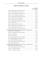
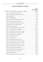
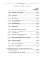
TABLE OF CONTENTS - Continued
Page No.
WP Sequence No.
TROUBLESHOOTING PROCEDURES - WINCH AND RIGHT-HAND WHEEL
CONTROL INOPERATIVE.
......................................................................................................
WP
0019
Figure 1. Directional Control Valve (DCV) Bank.
.........................................................................
0019-2
Figure 2. Hydraulic Diagnostic Center (HDC) Control Box.
.........................................................
0019-
3
Figure 3. Main Relief Valve 13L.
..................................................................................................
0019-
4
Figure 4. Directional Control Valve (DCV) Bank.
.........................................................................
0019-
5
Figure 5. Hydraulic Diagnostic Center (HDC) Control Box.
.........................................................
0019-
5
Figure 6. Hydraulic Diagnostic Center (HDC) Control Box.
.........................................................
0019-
7
Figure 7. Directional Control Valve (DCV) Bank.
.........................................................................
0019-
7
TROUBLESHOOTING PROCEDURES - WINCH WILL NOT PULL RATED LOAD.
........................
WP 0020
Figure 1. Winch Control and Ejector Lock.
..................................................................................
0020-2
Figure 2. Hydraulic Diagnostic Center (HDC) Control Box.
.........................................................
0020-3
Figure 3. Directional Control Valve (DCV) Bank.
.........................................................................
0020-
4
Figure 4. Hydraulic Diagnostic Center (HDC) Control Box.
.........................................................
0020-
5
Figure 5. Winch Relief Valve.
......................................................................................................
0020-
6
Figure 6. Directional Control Valve (DCV) Bank.
.........................................................................
0020-
6
Figure 7. Hydraulic Diagnostic Center (HDC) Control Box.
.........................................................
0020-
7
Figure 8. Winch Motor.
................................................................................................................
0020-
9
Figure 9. Winch Shift Linkage.
...................................................................................................
0020-
10
Figure 10. Winch Linkage.
.........................................................................................................
0020-
11
TROUBLESHOOTING PROCEDURES - APPARENT HYDRAULIC DIAGNOSTIC CENTER
(HDC) SYSTEM
PROBLEM.
....................................................................................................
WP 0021
Figure 1. Umbilical Cable Assembly W4 Connection to Umbilical Cable
Disconnect Bracket.
...........................................................................................................
0021-2
Figure 2. Umbilical Cable Assembly W4 Connections to Hydraulic Diagnostic
Center (HDC) Control Box.
................................................................................................
0021-
3
Figure 3. Hydraulic Diagnostic Center (HDC) System Ground Connection in Vehicle.
...............
0021-
3
Figure 4. Hydraulic Diagnostic Center (HDC) Control Box Front Panel.
.....................................
0021-
4
Figure 5. Vehicle Transmission in Neutral with Parking Brake Fully Engaged.
...........................
0021-
6
TM 5-2350-378-23&P
xi
Back to Top

