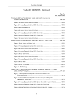
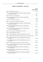
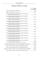
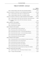
TM-5-2350-378-23-P - Page 25 of 644
TABLE OF CONTENTS - Continued
Page No.
WP Sequence No.
Figure 26. Umbilical Cable Assembly W4P2 and W4P3 Connections to Hydraulic
Diagnostic Center (HDC) Control Box.
............................................................................
0021-
26
Figure 27. Umbilical Cable Assembly W4P2 and W4P3 Electrical Connections.
......................
0021-
27
Figure 28. Umbilical Cable Assembly W4P5 and W4P6 Electrical Connections.
......................
0021-
27
Figure 29. Umbilical Cable Assembly W4 Connection to Umbilical Cable
Disconnect Bracket.
.........................................................................................................
0021-
29
Figure 30. Pin Locations for W2J1 and W3J1 Connectors.
.......................................................
0021-
30
Figure 31. Upper Cable Assembly W2 and Lower Cable Assembly W3 Electrical
Connections.
....................................................................................................................
0021-
30
Figure 32. Umbilical Cable Assembly W4 Connections to Hydraulic Diagnostic
Center (HDC) Control Box.
..............................................................................................
0021-
31
Figure 33. Umbilical Cable Assembly W4P2 and W4P3 Electrical Connectors.
.......................
0021-
32
Figure 34. Umbilical Cable Assembly W4P5 and W4P6 Electrical Connectors.
.......................
0021-
32
Chapter 3 - PREVENTIVE MAINTENANCE CHECKS AND SERVICES (PMCS)
MAINTENANCE INSTRUCTIONS
PREVENTIVE MAINTENANCE CHECKS AND SERVICES (PMCS) INTRODUCTION.
..................
WP 0022
PREVENTIVE MAINTENANCE CHECKS AND SERVICES (PMCS).
...............................................
WP 0023
Table 1. Preventive Maintenance Checks and Services (PMCS).
...............................................
0023-1
Figure 1. Bolt.
..............................................................................................................................
0023-1
Figure 2. Hydraulic Diagnostic Center (HDC) Bracket.
................................................................
0023-2
Figure 3. Hydraulic Diagnostic Center (HDC) Control Box.
.........................................................
0023-3
Figure 4. Hydraulic Hoses, Tubes, and Fittings.
..........................................................................
0023-3
Figure 5. Hydraulic Metal Tubes.
.................................................................................................
0023-4
Chapter 4 - MAINTENANCE INSTRUCTIONS
SERVICE UPON RECEIPT.
..............................................................................................................
WP 0024
M9 ACE HYDRAULIC DIAGNOSTIC CENTER (HDC) SYSTEM FUNCTIONAL CHECK-OUT.
......
WP 0025
Figure 1. Directional Control Valve (DCV) Bank.
.........................................................................
0025-2
Figure 2. Typical Hydraulic Diagnostic Center (HDC) Control Box Test Display
(Not The Start-up Display).
................................................................................................
0025-
4
Table 1. Default Solenoid Valve LCD Display.
............................................................................
0025-
5
TM 5-2350-378-23&P
xiii
Back to Top


