TM-5-2350-378-24-P - Page 390 of 790
TM 5--2350--378--24&P
0016 00--87
HYDRAULIC OIL OVERHEATS -- Continued
0016 00
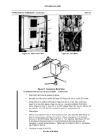
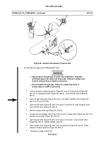
Figure 62. HDC Control Box
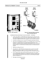
Figure 63. Suspension Raise/Lower Relief
Valve 3L and Relief Valve 3R
SUSPENSION RAISE/LOWER RELIEF VALVE ADJUSTMENT -- CONTINUED
For 3R; Using LINE UP or LINE DOWN button (Figure 62, item 3), select V15 on the
HDC display (Figure 62, item 2). Close V15 on the HDC display (Figure 62, item 2) by
selecting the CHANGE POSITION button (Figure 62, item 4) on the HDC control box.
Loosen jam nut (Figure 63, item 1) on port 3R of suspension raise/lower relief valve.
With right--hand SUSPENSION CONTROL lever in the RAISE position, while observing
transducer T--1 hydraulic pressure on the HDC display (Figure 62, item 1), turn
suspension raise/lower relief valve 3R adjusting screw (Figure 63, item 2), clockwise to
increase pressure or counterclockwise to decrease pressure, until desired pressure is
indicated.
Tighten jam nut (Figure 63, item 1).
Using LINE UP or LINE DOWN button (Figure 62, item 3), select V15 on the HDC
display (Figure 62, item 2). Open V15 on the HDC display (Figure 62, item 2) by
selecting the CHANGE POSITION button (Figure 62, item 4) on the HDC control box.
For 3L; repeat the above steps closing and opening solenoid valve V16, using the
left--hand SUSPENSION CONTROL lever, adjusting the suspension raise/lower relief
valve 3L adjusting screw (Figure 63, item 2) for port 3L, and monitoring the hydraulic
pressure at transducer T--1.
Stop engine; relieve hydraulic pressure.
Back to Top


