TM-5-2815-241-34-P - Page 206 of 738
TM 5-2815-241-34&P
CYLINDER HEAD - CONTINUED
ACTION
LOCATION
ITEM
REMARKS
INSPECTION - CONTINUED
15.
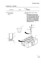
Cylinder head (1)
16.
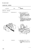
Injector
assembly (2)
Injector tip (5)
a.
Using 1/2-inch drive 1/2-inch socket,
3-inch extension, and ratchet handle,
install injector assembly. Secure with
clamp (3) and capscrews (4).
b.
Using 1/2-inch drive 0 to 175 ft lb (0 to
245 N•m) torque wrench, tighten cap-
screws alternately in 4 ft lb (5.4 N•m)
increments to 10 to 12 ft lb (14 to 16.8
N•m).
Using ST-547 dial indicator and ST-981
injector tip protrusion checking tool (6),
measure injector tip protrusion.
Injector tip protrusion must be
0.060 to 0.070 Inch (1.52 to 1.78
mm). If Injector tip protrusion Is not
within these specifications, tag in-
jector sleeve (7) for replacement.
See pages 35 thru 48.
TA 242457
2-184
Back to Top


