TM-5-3805-254-14-P-2 - Page 560 of 894
TRUCK SERVICE MANUAL
FUEL SYSTEM
turbochargers, since this varies automatically with speed and
load of engine.
If turbocharger runs too fast, it indicates the
engine is being overfueled.
Overfueling may cause
turbocharger failure.
Vibration
If noticeable vibration develops in turbocharger, shut down
engine and find cause.
Vibration might be caused by damage
to compressor wheel, shaft or turbine wheel.
Inlet Air Restriction
If inlet air restriction exceeds 25 inches [635 mm] of water
under conditions stated below, air flow to cylinders will not be
sufficient and a loss of power will occur.
Excessive exhaust
smoke and excessive exhaust temperatures will also
accompany loss of power.
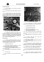
1.
Check inlet air restriction by attaching a vacuum
gauge or water manometer in air intake piping.
Adapter must
be perpendicular to air flow and one pipe diameter upstream
from turbocharger in a straight section of tubing.
Fig.
104.
Fig.
104, TA2.
Checking air inlet restriction
2.
Operate engine until normal operating temperature is
reached.
3.
Operate engine at rated speed and full-load; take
reading from vacuum gauge or manometer.
4.
If air restriction exceeds 25 inches [635 mm] of water:
a.
Clean or replace dry-type cleaner element.
b.
Replace damage air piping, rain shield or housing.
c.
Remove excessive bends or other source of
restriction in air piping.
5.
Air restriction readings may be taken at air cleaner
outlet connection plug.
If reading is taken at air cleaner,
restriction must not exceed 20 inches [508 mm] of water.
Note:
Engines with a properly operating restriction gauge
mounted in the air cleaner outlet need not be checked in the
preceding
manner
Refer
to
applicable
Engine Maintenance
Manual for further details.
Exhaust Back Pressure
Exhaust back pressure is a significant indication of exhaust
system conditions and piping layout.
High pressure indicates
restrictions caused by foreign objects or excessive bends in
exhaust piping or use of piping smaller than exhaust outlet of
turbocharger.
The lowest pressure obtainable is desired.
If exhaust back pressure exceeds 2 inches [50.8 mm] of
mercury, early engine failure and poor performance may be
expected.
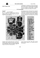
To check exhaust back pressure,
1.
Point of measurement must be as close as possible
to turbocharger outlet flange in an area of uniform flow such as
a straight section of pipe at least one pipe diameter from any
changes in flow area or flow direction.
Where it is impossible
to locate point of measurement in a straight section, it is
permissible to measure on side of a bend where flow is
uniform and equivalent to flow along centerline.
Do not
measure on inside or outside radius of bend as flow is not
uniform at these points.
Fig.
105.
Fig.
105, TA3.
Checking exhaust back pressure
2.
At point selected, weld a 1/8 inch [3.18 mm] pipe
coupling to exhaust tubing.
Drill through tubing with a 1/8 inch
drill.
Remove all burrs.
Mount 90 deg.
Weather head fitting
to coupling, then use 3 ft.
[0.9 m] of 1/8 inch I.D.
copper
tubing (to resist heat) plus 10 ft. [3 m] of 3/16 inch [4.8 mm]
I.D.
soft rubber hose to manometer.
The manometer may be
mercury
filled
or
water
filled.
555
Back to Top


