TM-5-3805-254-14-P-2 - Page 652 of 894
STEERING
TRUCK SERVICE MANUAL
NOTE:
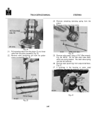
On late production series
steering gears install a new retaining pin
to proper depth and replace roll pin.
20.
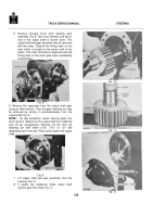
Position a new 0ring seal on housing cover.
Install cover assembly.
It may be necessary to
use a soft hammer to tap the cover in place.
21.
Install
the
bolts
and
torque
to
proper
specifications.
22.
The relief valve plungers with the jam nuts may
now be installed using new O-rings.
Turn them
approximately six turns.
Final adjustment of the
plungers is made when the steering gear is
installed on the vehicle.
FINAL ADJUSTMENTS
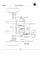
Bleeding Air from System
After reinstalling the steering gear on the vehicle
but prior to installing the pitman arm, bleed the air from
steering system in the following manner:
1.
Fill pump reservoir with SAE-10W-30 engine oil.
It will be necessary to continue filling after
starting the engine and during the bleeding
operation until correct oil level is maintained.
2.
Set parking brake or block wheels.
Start engine
and allow it to operate at fast idle speed.
3.
With engine running turn steering wheel from left
to right and return, making three complete cycles
to remove all air from the steering system.
4.
Stop engine.
PITMAN ARM INSTALLATION
NOTE:
To provide proper alignment of
the pitman arm to the output shaft, an
arrow is stamped on the arm and a dot
(or indentation) is on the output shaft
end.
These marks must always be in
alignment when the pitman arm is
installed on the output shaft.
There are two methods of retaining the pitman
arm on the output shaft:
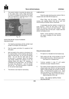
1.
Two setscrews are threaded into the pitman arm
and are tightened into a "V" type groove in the
output shaft.
Setscrews are either equipped with
a Nylock insert or jam nut to secure setscrews in
place, Fig.
35.
Fig .
35
With this method of retaining the pitman arm on the
output shaft, two procedures are used when installing the
arm.
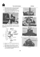
If the output shaft is equipped with a 1/2" x 20ONF or
9/16" x 18NF hole, a bolt approximately 4-1/4" long, an
adapter (large socket) and flat washer can be assembled
as shown in Fig.
36.
Tighten the bolt to force the pitman
arm on the shaft.
After the 1/2" bolt is tightened to 85 ft.
lbs.
or 9/16" bolt is torqued to 125 ft.
lbs., the two
setscrews are tightened to 15 ft.
lbs. and then the jam
nut tightened.
The 1/2" bolt, adapter and washer are
then removed.
If the end of the output shaft is not equipped with either a
1/2" or 9/16" threaded hole, the pitman arm should be
forced on the output shaft with a hammer.
The setscrews are then tightened to 12 ft. lbs.
If jam
nuts are used, tighten them now.
Back to Top

