TM-5-3805-254-34 - Page 184 of 727
TM 5-3805-254-34
6-8.
TRANSMISSION REPLACEMENT.
This Task Covers:
a.
Removal
b.
Installation
Initial Setup:
Equipment Conditions:
Equipment Conditions (Con’t):
•
Hydraulic fluid drained (see TM 5-3805-254-20).
•
Transmission to auxiliary transmission propeller shaft
•
Floorboards and inserts removed (see paragraph
removed (see paragraph 7-1).
15-3).
•
Frame tie tube removed (see paragraph 14-3).
•
Transmission oil pressure gage line and fittings
•
Transmission wiring harness leads tagged and
removed (see TM 5-3805-254-20).
disconnected (see paragraph 5-6).
•
Power take-off removed (see paragraph 16-1).
•
Transmission cooler hoses disconnected (see para-
Materials/Parts:
graph 6-5).
•
Marker tags (Item 25, Appendix B)
•
Transmission modulator valve removed (see para-
•
Four lockwashers
graph 6-7).
•
Exhaust pipe removed (TM 5-3805-254-20).
Tools/Test Equipment:
•
Transmission oil filler tube and dipstick removed (see
•
General mechanic’s tool kit
TM 5-3805-254-20).
•
Field automotive shop set
•
Transmission shift cable disconnected (see TM 5-
3805-254-20).
Personnel Required:
Two
a.
REMOVAL
1.
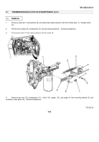
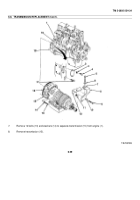
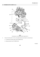
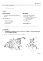
Remove two screws (4), lockwashers (3), and housing cover (2) from right side of engine flywheel housing (18).
Discard lockwashers.
CAUTION
Rotate engine only in normal operating direction to prevent damage to engine.
NOTE
Normal rotation of engine is clockwise when facing front of engine.
2.
While rotating engine to each of 12 screws (17), remove screws to disconnect flywheel (16) from engine flex plate
(19).
WARNING
Transmission is heavy.
DO NOT remove screws unless transmission is supported.
Failure to follow this warning may result in Injury or death to personnel.
3.
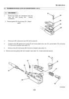
Support transmission (15) with transmission floor jack.
4.
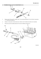
Remove nut (11), bolt (5), and washer (6) holding transmission rear mounting bracket (8) to crossmember (12).
5.
Remove rubber mount (7) from transmission rear mounting bracket (8).
6.
Remove two bolts (9), lockwashers (10), and transmission rear mounting bracket (8).
Discard lockwashers.
6-58
Back to Top

