TM-5-3805-254-34 - Page 562 of 727
TM 5-3805-254-34
15-4.
CAB ASSEMBLY MAINTENANCE (Cc
Equipment Conditions (Con’t):
• Air cleaner and brackets removed (see TM 5-
3805-254-20).
• Air cleaner lines removed from firewall (see TM
5-3805-254-20).
• Oil filter removed (see TM 5-3805-254-20).
• Body and chassis wiring removed (see para-
graph 5-6).
• Reverse polarity protection removed (see para-
graph 5-6).
• Transmission cable hood removed (see para-
graph 5-6).
• Floormats removed (see paragraph 15-2).
• Floorboards and Inserts removed (see para-
graph 15-3).
• Cab doors and hinges removed (see paragraph
15-16).
• Heater box removed (see paragraph 15-35).
• Instrument panels removed (see paragraph 15-
22).
• Instrument panel pad removed (see paragraph
15-21).
• Headlining removed (see paragraph 15-23).
• Coat hook removed (see paragraph 15-6).
Equipment Conditions (Con’t):
• Windshield glass removed (see paragraph 15-
25).
• Rear glass removed (see paragraph 15-26).
• Engine cover removed (see paragraph 15-1).
• Sunvisors removed (see paragraph 15-19).
• Cowl ventilator removed (see paragraph 15-11).
• Air intake duct removed (see paragraph 15-12).
• Cab door opening weatherseal removed (see
paragraph 15-8).
Materials/Parts:
• Four lockwashers
• Ninety-seven rivets
Tools/Test Equipment:
• General mechanic's tool kit
• Field automotive shop set
References:
• TM 9-237
1.
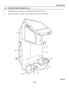
Remove two nuts (8), spacers (7), screws (1), four brackets (2 and 6), and bushings (3 and 5) from cab assembly
(28) and bracket (4).
2.
Remove four screws (17), flatwashers (18), and lockwashers (16) from upper mounting bracket (15).
Discard
lockwashers.
3.
Remove two nuts (27), screws (14), flatwashers (13), rebound insulators (12), flatwashers (11), rebound insulators
(10), and rebound retainers (9) from upper mounting bracket (15).
WARNING
Stand clear of lifting device when raising or lowering cab assembly.
Failure to follow this warning
may result In serious Injury or death.
4.
Using a suitable lifting device, carefully remove cab assembly (28) from frame.
5.
Remove upper mounting bracket (15) and mounting insulator (19) from lower mounting bracket (21).
6.
Remove four nuts (26), screws (20), and lower mounting bracket (21) from mounting crossmember (22).
7.
If damaged, remove 12 nuts (23), screws (25), and mounting crossmember (22) from bracket (24).
15-14
Back to Top


