TM-5-3805-264-13-P - Page 437 of 660
INSTALLATION
NOTE
Use antiseizing tape on all pipe threads (WP 0072).
1.
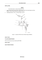
Apply antiseizing tape to pipe threads of nipple (Figure 2, Item 3) and install nipple and elbow
(Figure 2, Item 2) on filter housing cover (Figure 2, Item 4).
2.
Install gauge (Figure 2, Item 1) on elbow (Figure 2, Item 2).
Figure 2.
Hydraulic Oil Filter Service Indicator Gauge Installation.
END OF TASK
FOLLOW-ON MAINTENANCE
Remove body props and lower dump body (WP 0005).
END OF TASK
END OF WORK PACKAGE
TM 5-3805-264-13&P
0069
0069-3/blank
Back to Top


