TM-5-3805-274-13-P - Page 11 of 364
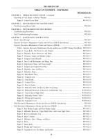
TABLE OF CONTENTS - CONTINUED
WP Sequence No.
CHAPTER 2 – OPERATOR INSTRUCTIONS - Continued
Operation in Cold, Rainy, or Snowy Weather .
...................................................................................
WP 0013
Figure 1. Control Lever Head .
...................................................................................................
WP 0013-1
CHAPTER 3 – TROUBLESHOOTING MASTER INDEX
Troubleshooting Master Index .
............................................................................................................
WP 0014
CHAPTER 4 – TROUBLESHOOTING PROCEDURES
Troubleshooting Procedures .
................................................................................................................
WP 0015
Field Troubleshooting Procedures .
.......................................................................................................
WP 0016
CHAPTER 5 – MAINTENANCE INSTRUCTIONS
Service Upon Receipt .
..........................................................................................................................
WP 0017
Operator Preventive Maintenance Checks and Services (PMCS) Introduction .
................................
WP 0018
Operator Preventive Maintenance Checks and Services (PMCS) .
.....................................................
WP 0019
Table 1. Operator Preventive Maintenance Checks and Services for M917 Dump Truck Body . WP 0019-2
Figure 1. Cargo Body, Cab Protector, and Tailgate .
................................................................
WP 0019-2
Figure 2. Hydraulic Hoses, Reservoir, and Pump .
...................................................................
WP 0019-2
Figure 3. Clearance Lamps and Marker Lamps .
.......................................................................
WP 0019-3
Figure 4. Tailgate Control Handle .
............................................................................................
WP 0019-4
Figure 5. Jaws, Lock Mechanism, and Hinge Pins .
..................................................................
WP 0019-4
Figure 6. Adjustment Chains and Chain Guides .
.....................................................................
WP 0019-5
Figure 7. Tailgate and Tailgate Pivot Pins .
...............................................................................
WP 0019-5
Figure 8. Hydraulic Lines and Hoses .
.......................................................................................
WP 0019-6
Figure 9. Hydraulic Pump .
.........................................................................................................
WP 0019-6
Figure 10. Pilot Relief Valve .
....................................................................................................
WP 0019-7
Figure 11. Control Lever .
..........................................................................................................
WP 0019-7
Figure 12. Grip Handle .
.............................................................................................................
WP 0019-8
Figure 13. Control Valve .
..........................................................................................................
WP 0019-8
Figure 14. Hoist Cylinder .
.........................................................................................................
WP 0019-9
Figure 15. Hydraulic Filter and Service Indication Gauge .
......................................................
WP 0019-9
Figure 16. Hydraulic Reservoir, Connectors, and Breather Cap .
...........................................
WP 0019-10
Figure 17. Top Oil Level Sight Glass .
....................................................................................
WP 0019-10
Figure 18. Hydraulic Control Valve .
.......................................................................................
WP 0019-11
Figure 19. Wiring and Connector .
...........................................................................................
WP 0019-11
Figure 20. Tarpaulin Cover .
.....................................................................................................
WP 0019-12
Field Preventive Maintenance Checks and Services (PMCS) Introduction .
......................................
WP 0020
Field Preventive Maintenance Checks and Services (PMCS) .
...........................................................
WP 0021
Figure 1. Side Marker Lights and Rear Marker Lights .
...........................................................
WP 0021-2
Figure 2. Hydraulic Reservoir, Upper Sight Glass, and Lower Sight Glass .
..........................
WP 0021-2
Figure 3. Reservoir Breather Cap .
.............................................................................................
WP 0021-3
Figure 4. Hoist Cylinder .
...........................................................................................................
WP 0021-4
Figure 5. Hydraulic Lines, Fittings, and Hoses .
.......................................................................
WP 0021-4
Figure 6. Filter .
...........................................................................................................................
WP 0021-5
Figure 7. Dump Body .
...............................................................................................................
WP 0021-5
Figure 8. Wiring and Connectors .
.............................................................................................
WP 0021-6
Figure 9. Tarpaulin Cover, Tie Straps, and Eyelets .
................................................................
WP 0021-7
TM 5-3805-274-13&P
iii
Back to Top

