TM-5-3805-274-13-P - Page 16 of 364
HOW TO USE THIS MANUAL
ABOUT YOUR MANUAL
Equipment operators shall familiarize themselves with the format and use of this TM prior to operating
equipment or performing routine maintenance. Learning how to use this manual will enable personnel to
quickly locate information, gain proper knowledge of the equipment, and shorten the time necessary to
complete the required procedure.
Features of this TM are:
Work Package Format –
This TM is organized in work package (WP) format. Each WP is an individual,
stand alone unit of information identified by a four-digit sequence number. WPs are positioned within the TM
in sequential order (i.e. 0001, 0002, 0003, etc.), and each WP is page numbered consecutively after the
sequence number at the bottom of each page (i.e. 0001-1, 0001-2, 0001-3, etc.). A WP may contain as many
as 30 pages.
Text Design –
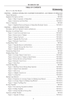
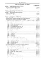
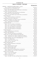
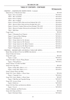
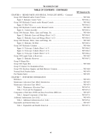
A Table of Contents (TOC) is located in the front matter section of the TM. WP titles and
sequence numbers are listed in the TOC in sequential order. WPs are organized into chapters based on subject
and chapters listed in the TOC. Chapter title pages are positioned sequentially within the manual and each
chapter title page contains an index of the WPs in that chapter only. In addition to the TOC and chapter title
pages, a separate subject index is located in the rear matter section of the TM. The subject index is organized
in alphabetical order with WP sequence and page numbers provided.
Use of Text and Illustrations –
Task steps and illustrations are located side-by-side on facing two-page
modules. Part nomenclature is identified by text callout numbers that correspond to illustration callout
numbers. Illustrations are presented with exploded views, cutaway views, and individual callouts numbered
sequentially, starting at the 11 o’clock position and continuing clockwise around each illustration. Tables and
figures are numbered sequentially within each WP. Abbreviations and acronyms are spelled out within the text
the first time they appear in the manual only. A list of all abbreviations and acronyms used in this TM is
provided in General Information, WP 0001.
HOW TO USE THIS MANUAL
The format of this manual is designed to make accessing information quick and easy. The following example
is intended as a guide and should be reviewed and put to memory before attempting to use this manual. If you
have any questions after reviewing the following example, ask your supervisor.
PROBLEM: While operating the Dump Truck Body you observe that the dump bed will not rise when the
T-handle lever is moved to the up position on the hydraulic control lever.
SOLUTION: Find information on the hydraulic control lever in the manual, review the operating procedures,
and if necessary, perform the appropriate troubleshooting tasks to solve the problem.
1. Refer to the TOC to determine what chapter and WP contains information on operation of the hydraulic
control lever. If there is not an obvious WP title that indicates information on operation of the levers, you
may locate the information more quickly using the subject index. After reviewing the TOC and/or subject
index, you determine that Chapter 2, Operating Instructions, WP 0005, and Chapter 3, Troubleshooting
Procedures, WP 0015, contain the information you desire.
2. Go to WP 0005 and review the operating procedures pertaining to operating the lever. Go to WP 0014
and look through the list of malfunctions in the Operator Troubleshooting Index until you identify the
malfunction that most accurately fits the problem.
3. Go to WP 0015, Symptom – Dump body does not rise when control lever is placed in up position, and
follow the steps listed. As you perform the troubleshooting procedure you discover the linkage is loose.
Since disassembly of the hydraulic control lever assembly is not authorized at the operators level, notify
Field Maintenance as instructed.
4. Maintenance will refer to the TOC or subject index for maintenance filed troubleshooting and
maintenance procedures. In this example, go to Chapter 5, WP 0038 and/or WP 0039, and verify the
lever is at fault as determined at operator level. Using the TOC or subject index, find the maintenance
task for the hydraulic control valve. In this example, go to Chapter 4, WP 0038. Review the initial setup,
read the entire procedure, then perform the task steps in the order written, making sure you follow all
warnings, cautions, and notes. As you disassemble and inspect the hydraulic control valve you discover
and remove a damaged lever in the hydraulic control valve. The obvious cause of the problem. You must
complete the task, test and verify the dump truck body operates, and return it to service.
TM 5-3805-274-13&P
viii
Back to Top


