TM-5-3895-371-10 - Page 16 of 103
TM 5-3895-371-10
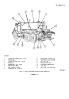
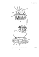
(21) Air Cylinder - There are a total of five air cylinders that provide directional force to shift,
raise, lower, and tilt the
spray bar.
(22) Spray Bar - The spray bar can be adjusted from eight to twenty-four feet with one and two foot sections. The
end sections are tapered to aid in draining and may be folded for traveling The bar can be shifted fourteen inches laterally
(seven inches each side of center) to follow a given line Normal operation requires an eight foot spread The height of the
spray bar is adjustable
(23) Discharge Header Strainer - Strains the bitumen after it leaves the pump and before it is distributed through the
control valves. Removes contaminants from the bitumen
(24) Loom Bumper - Protects the equipment mounted on the rear of the distributor from being hit accidentally Also
houses the rear side marker, backup, turn and clearance, blackout, and tall and stop lights and the wire harness for the
lights.
(25) Vacu-Flo Valve Lever - The vacu-flo works in conjunction with the quadrant control to route bitumen from the
spray bar and fill system back into the storage tank for filling and cleaning operations Vacu-flo valve positions are
(a) Vacuum off for filling
(b) Cleaning left half bar only
(
c) Cleaning right half bar only
(d) Cleaning entire bar
(26) Butterfly Valve Lever - Regulates pressure in the right side return line to tank. Butterfly valve is left open for all
operations except it is partially closed during hand spray operations to regulate pressure
(27) Intake Valve Lever - The intake valve shuts off the system at the pump (when operations are complete) to
prevent leakage from the tank through the system.
(28) Low Pressure Atomizing Burners - The low pressure burners operate on diesel fuel from a storage tank.
The
burners are mounted at the rear of the tank with ignition tiles located in the heating flues. The burners are supplied with a
combination of air and fuel by a combination burner blower and burner fuel pump.
(29) Air Relief Valve - The air relief valve vents excess air pressure from the burner blower.
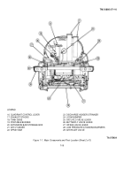
(30) Hydraulic Pump - The pump is an axial piston type with an infinitely variable displacement.
Minimum
displacement is 4 5 cubic inches per revolution.
The pump operates off the truck chassis PTO and supplies hydraulic
pressure to operate the hydraulic motor.
(31) Bitumen Pump - This heavy-duty gear-type pump is driven by the hydraulic motor through a double universal
joint and sealed bearing, with overload protection.
The pump has a delivery capacity of 400 gallons per minute and
supplies material to a 24 foot spray bar with sufficient pressure to produce an even fan-like spray from all nozzles, at any
specified rate between 0 10-1 0 gallons per square yard.
(32) Hydraulic Motor - The motor is an axial piston type with a fixed displacement of 4 88 cubic inches. The motor
powers the bitumen pump.
1-6
Back to Top

