TM-5-3895-372-20 - Page 18 of 694
TM 5-3895-372-20
Section II POWER TRAIN
2-4.
INTRODUCTION.
The mixer body is mechanically driven by the truck engine.
The power train is located on the left side of the unit.
It
provides power for all mixer body systems except the lamps and the electric winch.
2-5.
DESCRIPTION.
1.
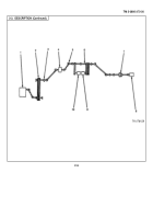
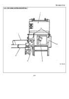
POWER TAKEOFF (PTO).
Supplies engine power to mixer body.
When engaged, meshes with transmission
gears to turn PTO shaft.
(See TM 9-2320273-20).
2.
PTO V-BELTS (5).
Driven by PTO jackshaft.
Turn main drive.
3.
BEARINGS BLOCKS (10).
Hold PTO jackshaft and main drive in place.
Bearings allow shafts to turn freely.
4.
REVERSING GEAR BOX.
Reverses direction of shaft rotation.
5.
UNIVERSAL JOINTS (8).
Transmit rotation between two shafts mounted at an angle.
6.
MAIN DRIVE.
Driven by PTO V-belts.
Rotating shaft powers water pump, hydraulic pump, and angle drive
gear box.
7.
MAIN CLUTCH.
When engaged, connects main drive to angle drive gear box.
Manually
8.
ANGLE DRIVE GEAR BOX.
Powered by main drive when main clutch is engaged.
Turns sand and stone
conveyor belt, cement meter-feeder, and dry admix feeder.
Output shaft mounted at right angle to main drive.
9.
HYDRAULIC PUMP.
Driven by six V-belts from main drive.
Powers mixer-auger.
10.
WATER PUMP.
Driven by two V-belts from main drive.
Pumps water for concrete mixing and cleanup.
2-4
Back to Top

