TM-5-3895-372-20 - Page 22 of 694
TM 5-3895-372-20
Section IV ADMIX SYSTEMS
2-8.
INTRODUCTION.
The mixer body has three admix systems for adding chemicals or coloring to concrete.
The two liquid admix (exactorate)
systems are identical except for the tank capacities.
Both tanks are mounted on the right side of the mixer.
The liquid
admix systems are described in paragraph 2-9.
The dry admix system, mounted on the right rear of the cement bin, adds powdered chemicals and colorings to concrete.
It is maintained at the Organizational level.
2-9.
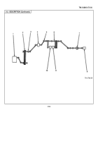
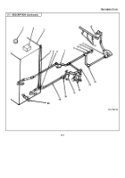
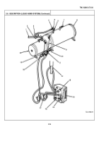
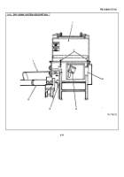
DESCRIPTION (LIQUID ADMIX SYSTEMS).
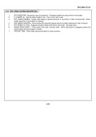
1.
AIR SUPPLY LINE.
Supplies dry compressed air from mixer body air system.
2.
AIR REGULATOR.
Controls air pressure to admix systems.
Operator turns handle to adjust pressure to 15
psi (103 kPa).
3.
AIR PRESSURE GAGE.
Indicates air pressure to admix tanks.
Normal reading is 141’ 15%1 psi (100-109
kPa).
4.
Al R GATE VALVES (2).
Block air pressure to each admix tank when that system is not in use.
Open to
admit pressure when admixture is needed.
5.
CHECK VALVES (2).
One-way valves prevent admixture solutions from backing up into
6.
RELIEF VALVES (2).
Automatically vent air when pressure exceeds 18-20 psi (124-138 kPa).
7.
Fl LL CAPS (2).
Used to fill admix tanks.
Vent on each cap allows operator to release pressure before
removing cap.
8.
HI-FLOW TAN K.
Pressure-tight tank holds 42 gal (160 liters) of liquid admixture.
9.
SIGHT GAGES (2).
Show level of liquid in each tank.
10.
DRAIN VALVES (2).
Allow draining of admixtures from tanks.
Also used when pumping admixture under
pressure into tanks.
11.
GAGE VALVES (4).
Close to prevent air and liquid from entering sight gages.
Top gage valves have vents
for bleeding pressure.
Bottom gage valves have draincocks.
12.
SPRAY NOZZLE.
Inject water and liquid admixture solutions into dry ingredients as they enter mixer-auger
trough.
13.
VENTS (4).
Open to prevent suction blocks when flowmeters and sight gages are drained.
14.
FLOWMETERS (2).
Floats in calibrated glass tubes indicate admixture flow.
15.
CONTROL VALVES (2).
Control liquid admixture flow.
Adjusted by control levers extending to front of
flowmeter assembly.
16.
DRAINCOCKS (6).
Used to drain admixture solutions from flowmeter assemblies and sight
17.
QUICK-ACTING VALVES (2).
Allow admixtures to flow from tanks through flowmeter to spray nozzle.
Mechanically linked to main clutch, opens automatically when main clutch is
18.
STRAINERS (2).
Wire screens filter admixtures flowing from tanks to flowmeter assembly.
19.
SOLUTION GATE VALVES (2).
Control flow of solutions from tanks to flowmeter assembly.
20.
LOW-FLOW TANK.
Pressure-tight tank holds 12 gal (45 liters) of liquid admixture.
2-8
Back to Top

