TM-5-3990-263-13-P - Page 106 of 728
OPERATION - Continued
14.
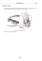
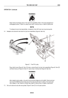
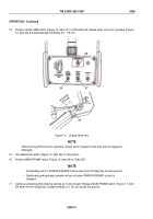
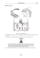
Position HOOK ARM switch (Figure 10, Item 27) to UNLOAD and release when hook arm cylinders (Figure
10, Item 26) are extended approximately 6 in. (15 cm).
6 inches
(15 cm)
26
27
28
29
Figure 10.
Unload Hook Arm.
NOTE
While moving LHS hook arm rearward, ensure winch hydraulic hose lines are not trapped or
damaged.
15.
Set HIGH IDLE switch (Figure 10, Item 28) to ON position.
16.
Position MAIN FRAME switch (Figure 10, Item 29) to UNLOAD.
NOTE
•
Immediately push in PARKING BRAKE control when rear of bridge bay touches ground.
•
Dashboard parking brake indicator will go out when PARKING BRAKE control is
released.
17.
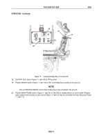
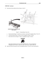
Continue unloading while steering vehicle as it rolls forward. Release MAIN FRAME switch (Figure 11, Item
29) when front of bridge bay is approximately 2 ft. (61 cm) above the ground.
TM 5-3990-263-13&P
0008
0008-10
Back to Top


