TM-5-3990-263-13-P - Page 138 of 728
OPERATION - Continued
CAUTION
•
Do not set PTO ENGAGE switch to ON with HIGH IDLE switch ON. Engaging the PTO
with HIGH IDLE switch ON may result in sudden application of hydraulic pressure to the
LHS. Failure to comply may result in damage to equipment.
•
PTO ENGAGE switch must be positioned OFF before road transport, or severe
equipment damage could result.
7.
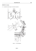
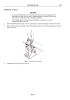
Set PTO ENGAGE switch (Figure 1, Item 7) to ON position. Indicator light (Figure 1, Item 8) will illuminate.
8.
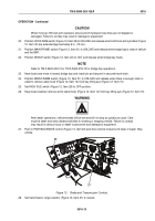
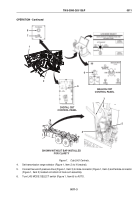
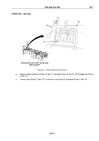
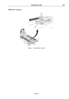
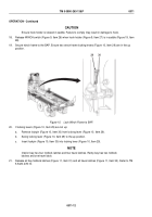
Ensure that curb-side and road-side front pin lock assemblies (Figure 2, Item 9) are engaged onto bay pins
(Figure 2, Item 10).
9
10
Figure 2.
Check Front Pin Locks.
9.
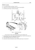
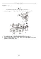
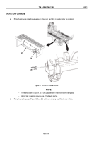
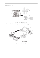
Install remote control unit (Figure 3, Item 11):
TM 5-3990-263-13&P
0011
0011-4
Back to Top

