TM-5-3990-263-13-P - Page 546 of 728
DISASSEMBLY - Continued
2.
Loosen four screws (Figure 1, Item 3), and remove cover (Figure 1, Item 4) from base (Figure 1, Item 5).
3.
Remove two screws (Figure 1, Item 6) and neck strap brackets (Figure 1, Item 2) from base (Figure 1, Item
5).
4.
Remove two screws (Figure 1, Item 7) and guard bars (Figure 1, Item 8) from base (Figure 1, Item 5).
5.
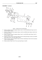
Remove spade connector (Figure 2, Item 9) and spade connector (Figure 2, Item 10) from ON/OFF switch
(Figure 2, Item 11).
9
10
12
15
11
13
16
20
14
19
18
22
23
17
21
Figure 2.
Remote Control Unit Disassembly.
6.
Remove spade connector (Figure 2, Item 12), spade connector (Figure 2, Item 13), and spade connector
(Figure 2, Item 14) from MAIN FRAME load/unload switch (Figure 2, Item 15).
7.
Remove spade connector (Figure 2, Item 16), spade connector (Figure 2, Item 17), and spade connector
(Figure 2, Item 18) from HOOK ARM switch (Figure 2, Item 19).
8.
Remove spade connector (Figure 2, Item 20), spade connector (Figure 2, Item 21), and spade connector
(Figure 2, Item 22) from WINCH switch (Figure 2, Item 23).
9.
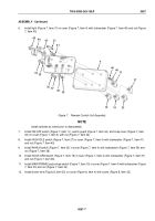
Remove two screws (Figure 3, Item 24), yellow wire (Figure 3, Item 25), and red wire (Figure 3, Item 26) from
HIGH IDLE switch (Figure 3, Item 27).
TM 5-3990-263-13&P
0067
0067-2
Back to Top


