TM-5-4210-249-13-P-1 - Page 1008 of 1188
TM 5-4210-249-13&P
0117-2
DRAFT
0117
NOTE
•
Do not open any valves during this step.
•
Remove all caps prior to applying air pressure.
•
Ensure system air pressure is at least 85 PSI (586 kPa) during this procedure.
•
Valves are open when tabs or yellow paint tabs are aligned with direction of fluid flow.
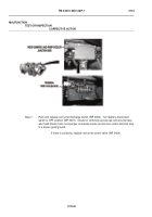
Step 1.
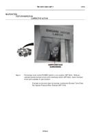
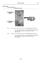
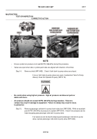
Install blow-out adapter to PASSENGER AUXILIARY INLET (WP 0044).
While an
assistant connects air hose to blow-out adapter (WP 0044), check if pressure is
displayed on PUMP DISCHARGE digital gauge (WP 0004).
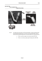
If pressure is displayed on PUMP DISCHARGE digital gauge,
repair (WP 0387) or replace passenger side auxiliary inlet valve (WP 0294).
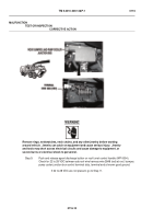
WARNING
ICON72
Be careful when using high air pressure.
High air pressure can blow out parts,
hoses, or debris with force.
Failure to comply could result in injury to personnel.
NOTE
•
Do not open any valves during this procedure except PASSENGER SIDE AUXILIARY.
Have an assistant maintain 50 PSI (345 kPa) during test.
•
Check all valves to ensure that more than one valve is not leaking.
•
Ensure system air pressure is at least 85 PSI (586 kPa) during this procedure.
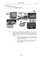
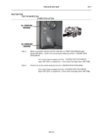
Step 2.
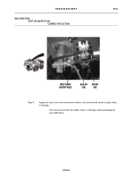
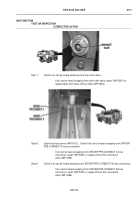
While an assistant operates PASSENGER AUX INLET valve control (WP 0004), check
if pressure is displayed on PUMP DISCHARGE digital gauge (WP 0004).
If pressure is not displayed on PUMP DISCHARGE digital display,
troubleshoot Passenger Side Auxiliary Inlet Valve Does Not Operate
Properly (WP 0113).
MALFUNCTION
TEST OR INSPECTION
CORRECTIVE ACTION
Back to Top

