TM-5-4210-249-13-P-2 - Page 314 of 1452
TM 5-4210-249-13&P-2
0152-8
DRAFT
0152
TFFT02624
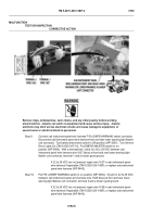
WARNING
ICON 3
Remove rings, wristwatches, neck chains, and any other jewelry before working
around vehicle.
Jewelry can catch on equipment and cause serious injury.
Jewelry
and tools may short across electrical circuits and cause damage to equipment, or
severe burns or electrical shock to personnel.
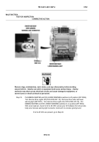
Step 9.
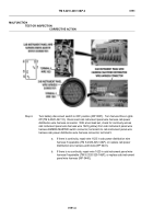
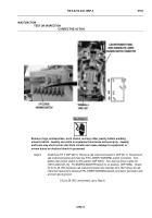
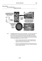
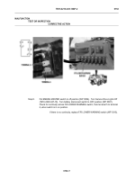
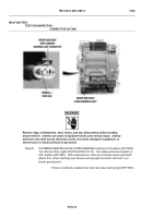
Connect cab instrument panel wire harness F/R LOWER WARNING switch connector.
Disconnect cab instrument panel wire harness front and rear lower warning light flasher
unit connector.
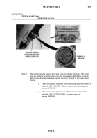
Turn battery disconnect switch to ON position (WP 0007).
Turn Service
Drive Lights On (TM 9-2320-347-10).
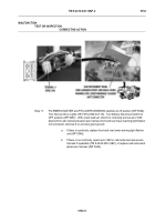
Put EMERG MASTER switch to on
position (WP 0004).
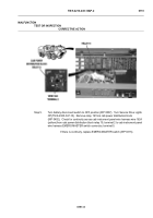
With a test lead set, check for 22 to 28 VDC between cab
instrument panel wire harness wire 1627 (blue) at front and rear lower warning light
flasher unit connector, terminal 1 and a known good ground.
If 22 to 28 VDC are not present, repair wire 1627 in cab instrument panel
wire harness if repairable (TM 9-2320-325-14&P), or replace cab instrument
panel wire harness (WP 0440).
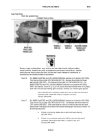
Step 10.
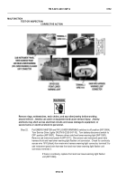
Put F/R LOWER WARNING switch to on position (WP 0004).
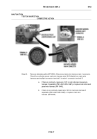
Check for 22 to 28 VDC
between cab instrument panel wire harness wire 1628 (blue) at front and rear lower
warning light flasher unit connector, terminal 2 and a known good ground.
If 22 to 28 VDC are not present, repair wire 1628 in cab instrument panel
wire harness if repairable (TM 9-2320-325-14&P), or replace cab instrument
panel wire harness (WP 0440).
MALFUNCTION
TEST OR INSPECTION
CORRECTIVE ACTION
Back to Top

