TM-5-4210-249-13-P-3 - Page 1033 of 1488
TM 5-4210-249-13&P-3
0495-3/(4 blank)
DRAFT
0495
INSTALLATION
1.
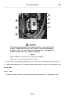
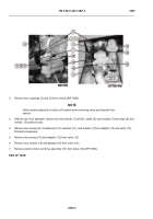
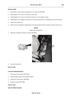
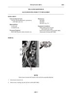
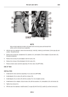
Install electric motor and drive assembly (17) on valve (13) (WP 0388).
2.
Install adapter (16) on valve (13) with four screws (15).
3.
Install adapter (12) on valve (13) with two screws (14).
Do not tighten screws.
4.
Install bracket (7) on adapter (12) and valve (13) with two washers (11), lockwashers (10), and screws (9).
5.
Tighten two screws (14).
6.
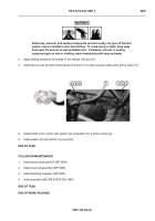
With the aid of an assistant, install bracket (7) on pipe (8) with U-bolt (5), cradle (6), and two locknuts (4).
NOTE
Install lower coupling first.
7.
Install two couplings (3) and (2) on vehicle (WP 0483).
8.
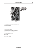
Connect connector (1).
END OF TASK
FOLLOW-ON MAINTENANCE
1.
Close pump house panel A (WP 0539)
2.
Install left splash guard (TM 9-2320-325-14&P)
3.
Install pump house panel I (WP 0540)
4.
Install flow sensor (WP 0390)
END OF TASK
END OF WORK PACKAGE
TFFT00746
Back to Top

