TM-5-4210-249-13-P-3 - Page 399 of 1488
TM 5-4210-249-13&P-3
0392-1
DRAFT
0392
FIELD LEVEL MAINTENANCE
GLOW PLUG CONTROL RELAY REPLACEMENT
INITIAL SETUP:
REMOVAL
-
-
-
-
-
-
-
-
-
-
-
-
-
-
-
-
-
-
-
-
-
-
-
-
-
-
-
-
-
-
-
-
-
-
-
-
-
NOTE
Tag and mark wires prior to removal to ensure proper installation.
1.
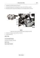
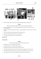
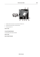
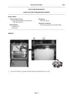
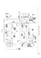
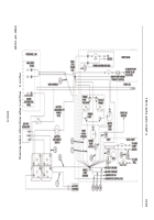
Remove retaining clip (1) and pump house wire harness connector (2) from glow plug control relay (3).
2.
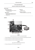
Remove nut (4) and wire 1413766 (5) from glow plug control relay (3).
3.
Remove nut (6) and wire 1413770 (7) from glow plug control relay (3).
NOTE
Wire 1413761 must be removed to access screw.
4.
Remove nut (8) and wire 1413761 (9) from circuit breaker (10).
-
-
-
-
-
-
-
-
-
-
-
-
-
-
-
-
-
-
-
-
-
-
-
-
-
-
-
-
-
-
-
-
-
-
-
-
-
TFFT04196
Tools and Special Tools
Tool Kit, General Mechanic’s: Automotive
(WP 0622, Item 27)
Materials/Parts
Compound, Sealing (WP 0625, Item 17)
Tags, Identification (WP 0625, Item 51)
Lockwasher (1)
References
WP 0615, Fig. 18
Equipment Conditions
Pump house panel S removed (WP 0540)
Back to Top

