TM-5-4210-249-13-P-3 - Page 979 of 1488
TM 5-4210-249-13&P-3
0486-1
DRAFT
0486
FIELD LEVEL MAINTENANCE
NO. 2 DISCHARGE VALVE (DRIVER SIDE) REPLACEMENT
INITIAL SETUP:
REMOVAL
NOTE
•
Tag and mark wire prior to removal to ensure proper installation.
•
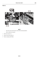
Valve shown removed with electric motor and drive assembly attached.
•
Remove cable ties as required.
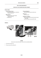
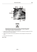
1.
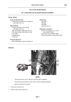
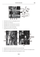
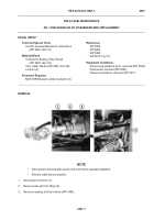
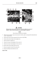
Disconnect connector (1).
2.
Remove hose (2) from elbow (3).
-
-
-
-
-
-
-
-
-
-
-
-
-
-
-
-
-
-
-
-
-
-
-
-
-
-
-
-
-
-
-
-
-
-
-
-
-
TFFT0784A
Tools and Special Tools
Tool Kit, General Mechanic’s: Automotive
(WP 0622, Item 27)
Materials/Parts
Compound, Sealing, Pipe Thread
(WP 0625, Item 21)
Tags, Identification (WP 0625, Item 51)
Ties, Cable, Plastic (WP 0625, Item 58)
Locknut (2)
Lockwasher (2)
Locknut (2)
Personnel Required
MOS 63B Wheeled vehicle mechanic (2)
References
WP 0388
WP 0483
WP 0489
WP 0615, Fig. 113
Equipment Conditions
Pump house panels A, D, E, and I
removed (WP 0540)
Flow sensor removed (WP 0390)
Pressure transducer removed (WP 0411)
Back to Top

