TM-5-5420-202-10 - Page 60 of 535
0004
TM 5-5420-202-10
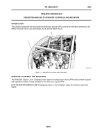
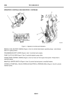
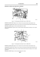
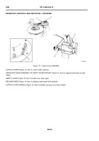
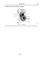
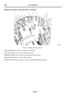
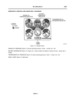
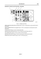
Figure 4.
Operator’s Controls and Indicators.
MANUAL FUEL SHUTOFF HANDLE (Figure 4, Item 2) controls transmission operating range. Locks brakes
when in P (park) position.
TRANSMISSION SHIFT LEVER (Figure 4, Item 1) controls fuel to engine.
PUMP CLUTCH LEVER (Figure 4, Item 3) controls hydraulic pump clutch.
PURGE PUMP CONTROL HANDLE (Figure 4, Item 4) forces air from engine fuel system. Pumps fuel to
manifold heaters.
MANIFOLD HEATER SWITCH (Figure 4, Item 5) controls fuel and power to manifold heaters.
HYDRAULIC PUMP BALL VALVE (HYDRAULIC/ELECTRICAL UPGRADE (HEU)) (Figure 4, Item 6) controls
hydraulic pump.
0004-4
OPERATOR’S CONTROLS AND INDICATORS - CONTINUED
Back to Top

