TM-5-5420-202-10 - Page 61 of 535
TM 5-5420-202-10
0004
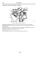
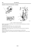
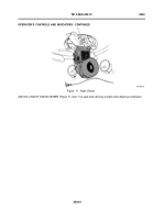
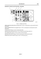
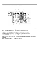
Figure 5.
Operator’s Controls and Indicators.
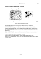
INDICATOR PANEL (Figure 5, Item 1) provides operator with operating controls and indicators.
MASTER CONTROL PANEL (Figure 5, Item 2) provides operator with operating controls and indicators.
INTERCOM CONTROL PANEL (Figure 5, Item 3) provides voice communication selection and volume control.
SEAT CONTROL HANDLE (Figure 5, Item 4) releases seat for forward or rearward adjustment. Locks seat at
desired position.
HEIGHT ADJUSTMENT LEVER (Figure 5, Item 5) releases seat for height adjustment. Locks seat at desired
height.
OPERATOR’S SEAT (Figure 5, Item 6) controls position of operator.
PUMP CLUTCH LEVER ASSEMBLY/PUMP BALL VALVE ASSEMBLY (FOR VEHICLES WITH
HYDRAULIC/ELECTRICAL UPGRADE (HEU)) (Figure 5, Item 7) provides power to hydraulic pump and pressure
for hydraulic system.
0004-5
OPERATOR’S CONTROLS AND INDICATORS - CONTINUED
Back to Top

