TM-5-5420-202-20-3 - Page 876 of 1060
TM 5-5420-202-20-3
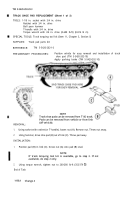
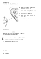
TRACK ASSEMBLY REPLACEMENT (Sheet 9 of 10)
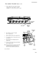
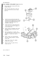
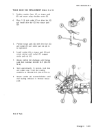
33. Using hammer, drive two end connectors (G)
onto two pins (H) held together by fixture (F)
clamps.
34. Leave 1/2 inch space between end connectors
(G) and fixtures (F).
35.
36.
37.
38.
39.
40.
41.
Place wedge (J) to underside of end connector
(G).
Using 15/16 inch socket, install bolt (K) through
wedge (J). Tighten bolt snug.
Install cap (L), bolt (M), centerguide (N), and
nut (P).
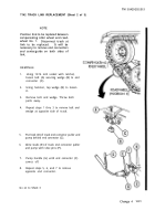
Using 1-5/16 inch socket and extension, tighten
nut (P) to secure centerguide (N) in place.
Using 1-5/16 inch socket and torque wrench or
torquing tool kit. torque nut (P) to 15-20 lb-ft
(20-27 IN-m).
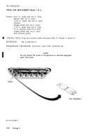
Remove track connecting fixtures (F).
Using hammer, drive both end connectors (G)
all the way onto link pins (H).
Go on to Sheet 9.1
Change 4
14-87
Back to Top

