TM-5-5420-203-14 - Page 24 of 298
TM 5-5420-203-14
1-6. EQUIPMENT CHARACTERISTICS, CAPABILITIES, AND FEATURES -
CONT
NOTE
The MLC 70 AVLB will support the M-1 tank with no greater risk than the MLC 60
incurs when supporting a normal capacity of class 60.
b. Equipment Capabilities.
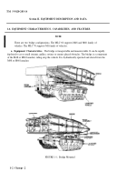
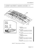
The MLC 60 bridge has a clear span of 60 ft; (See FIG. 1-2) a normal
capacity of Class 50; a caution rating of above 50 MLC; and a risk rating of above 61 MLC. When using
caution or risk crossings, usable span is reduced to 50 foot gap. It can accept crossing by the heavier,
wider M-l tank. Certain precautions must be followed to reduce the chance of a bridge failure with the
M-l tank and will be addressed in the Operating Instructions, Chapter 2. The typical mobility data is as
follows:
Ground clearance of vehicle .
............................................................
1 ft, 2 1/4 in.
Overhead clearance required .
...............................................................
13 ft, 1 in.
Width.
. ..................................................................................................
13 ft, 2 in.
Weight of vehicle and bridge.
. ..................................................................
63 tons
Grade-ascending ability.
. ..............................................................................
30 %
Vertical obstacle vehicle will climb .
......................................................
1 ft, 6 in.
Width of ditch vehicle will cross.
. .........................................................
8 ft, 6 in.
Typical clearance turning radius (average).
..................................................
44 ft
Fording depth.
..................................................................................................
4 ft
Treadways (width).
.................................................................................
5 ft, 2 in.
The launcher (with the bridge mounted) can exceed the rate of troop movement. The route chosen must
accommodate the height, width, and weight of the launcher with the bridge mounted. When possible,
routes should be taken to avoid serious obstacles, rough terrain, and heavily wooded areas, These routes
slow the launcher with the bridge down. The launchers have power for cross-country travel and can
make sharp turns. The high center of gravity of the bridge may cause a rocking sensation in the launcher
when traveling over rolling terrain with frequent dips and gullies. If this sensation becomes severe,
reduce the vehicle speed to solve the problem. The launcher with the bridge mounted requires more
fuel.
c. Equipment Features.
The bridge has an integral role in the movement of troops and/or supplies.
It helps the troops to cross obstacles such as ravines, gullies, creeks, small streams and rivers. It is easily
launched and available on the combination carrier/launcher. It is a girder bridge of aluminum alloy and
may be launched or retrieved from either end. The bridge is capable of sustained use for months.
Extended use or sustained periods of use require frequent inspections to ensure the reliability of the
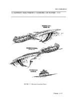
bridge. The bridge can be launched and retrieved either up or down hills with grades of 15%. The
bridge may be launched on side slopes up to 8% or any combination of up, down, and side slopes, (see
FIGURE 1-3). On level ground the launcher is not affected by muddy or marshy launching sites as long
as supportive base does exist. When launching on grades with muddy terrain, use care since the bridge
in the raised upright position creates a leveraged extension that can cause the launcher to slide or tilt.
These situations and others will be addressed in Chapter 2. Other bridges may be brought into use by a
flatbed carrier or a second launcher vehicle. These bridges can then be loaded on launcher vehicles and
can move forward with the troops. The bridge is a highly mobile, easily maintained and rapidly
deployable component of our combined fighting forces.
1-4 Change 2
Back to Top


