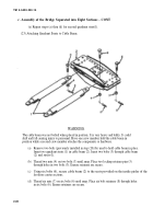
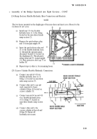
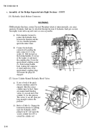
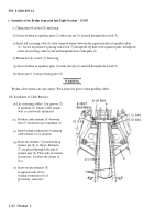
TM-5-5420-203-14 - Page 88 of 298
TM 5-5420-203-14
2-5. ASSEMBLY AND PREPARATION FOR USE OF MLC 70 - CONT
c. Assembly of the MLC 70 Bridge.
EQUIPMENT CONDITIONS :
Bridge separated into four sections.
TOOLS/EQUIPMENT:
General Mechanic’s tool Box, SC 5180-90-N26
Sledge Hammer (8-10 lb)
Pry Bars (5-6 A) (three required)
Wrench, Adjustable, (Item 3, Appendix B) (two required)
Lifting Device, 15,000 lb Minimum Lift Capability
Sling, Two leg (NSN TBD)
SUPPLIES:
Cribbing, 4x4x6 ft
PERSONNEL:
Ten
NOTE
When possible, assemble the bridge on a hard surface, within a unit compound, on an old
road bed, etc.
(1)
Installation of Holder Bracket (Near-Shore and Far-Shore)
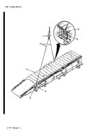
(a) Install holder bracket (1) on diaphragm
(2).
Align with holes on either side of top
of diaphragm. Place flat washer (3) on
bolt (4) and install through bracket (1).
Install lock washer (5) and nut (6) on bolt
(4). Tighten nut/bolt assembly. Repeat
for remaining bolt (4).
(b) Repeat step (a) for remaining holder
bracket (1) on opposite diaphragm (2).
2-38 Change 2
Back to Top

