TM-5-5420-203-14 - Page 82 of 298
(b)
(c)
(d)
TM 5-5420-203-14
c. Assembly of the Bridge Separated into Eight Sections - CONT
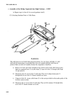
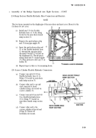
(c) Thread nut (4) on bolt (3) until snug.
(d) Secure bolt/nut in equalizer plate (2) with cotter pin (5) inserted through hole in bolt (3).
(e) Insert left scissoring cable (6) (note strand rotations) between the separated plates of equalizer plate
(2). Secure in position by placing socket bolt (7) through the top half of the equalizer plate, through the
eyelet of scissoring cable (6) and out through the base of the plate (2).
(f) Thread nut (8) on bolt (7) until snug.
(g) Secure bolt/nut in equalizer plate (2) with cotter pin (9) inserted through hole in bolt (7).
(h) Secure pm (11) using retaining pin (12).
WARNING
Broken cable strands can cause injury. Wear protective gloves when handling cables.
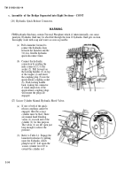
(29) Installation of Cable Retainer.
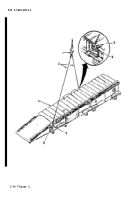
(a) Lay scissoring cables (1) in grooves (2)
of quadrant (3). Ensure cable strands
twist as previously instructed.
Position cable retainer (4) between
slots (5) located on top of quadrant (3).
Insert locking retainer pins (6) pinning
cable retainer (4) in position.
Insert one retainer (7) in each locking
retainer pin (6) as shown. Retainers
(7) are placed through both ends of
retainer pins (6). Flare ends of retainer,
if necessary, to reduce the chance of
loss.
Insert two pin retainers (8)
in opposite ends of two
(e)
locking retainer pins (6) if
previously removed.
2-32 Change 2
Back to Top

