TM-5-5420-203-14 - Page 99 of 298
TM 5-5420-203-14
c. Assembly of the MLC 70 Bridge -
CONT
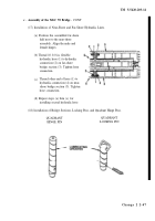
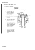
(19) Installation of Quadrant
NOTE
Ensure quadrant retaining holes are 4 1/2±1/2 in. from the surface of center section hinges
(a)
Using a lifting device and sling,
position the quadrant (1) facing
the near-shore end of bridge.
(b) Place the quadrant (1) in position
so that it rests on the installed
quadrant hinge pins (2).
(c)
Close the two coupling hinges (3)
and (4). Insert one quadrant
coupling hinge pin (5) through
each hinge from the center of the
bridge outward. Install pin
retainer (6) through quadrant
hinge pin.
(d)
Insert a second quadrant locking pin (7) from the rear, passing through the center pin
(2) and out between the hinges (3) and (4). Install second retainer (8) in quadrant
locking pin (7).
(e)
Repeat steps (c) and (d) for opposite side
(f)
Install a third quadrant locking pin (9) through the two angular plates (10) passing over
installed pin (7). Install retainer (11) in pin (9). Repeat for opposite side.
Change 2 2-49
Back to Top


