TM-5-5420-228-24 - Page 289 of 750
TM 5-5420-228-24
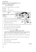
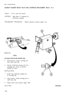
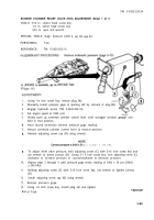
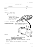
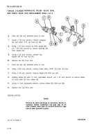
MASTER RELIEF VALVE (RV1) AND CHECK VALVE (CV1)
5.
6.
7.
8.
9.
10.
11.
12.
13.
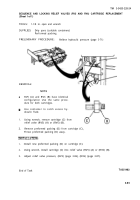
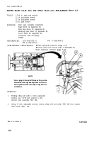
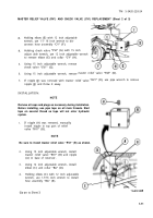
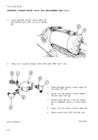
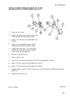
Using 15 inch adjustable wrench, install
check valve “CV1” (F) with flow arrow
pointing toward master relief valve
“RV1“ (B).
Holding check valve “CVI” (F) with 15
inch adjust able wrench, use 12 inch
adjustable wrench to install elbow (G)
and collar “CY” (H).
REPLACEMENT (Sheet 3 of 3)
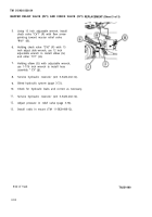
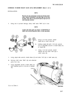
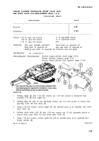
Holding elbow (G) with adjustable wrench,
use 1-7/16 inch wrench to install hose
assembly “ CY” (J).
Service hydraulic reservoir (LO 5-5420-202-12).
Bleed hydraulic system (page 3-72).
Check for hydraulic leaks and correct as necessary.
Service hydraulic reservoir (LO 5-5420-202-12).
Adjust pressure in relief valve (page 3-76).
Install radio in mount (TM 11-5820-498-12).
End of Task
3-92
TA251490
Back to Top

