TM-55-2350-215-10-15 - Page 57 of 66
TM 55-2350-215-10-15
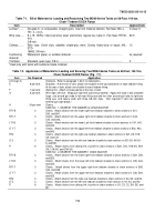
Table 7-6.
Bill of Materials for Blocking and Tiedown of M60-Series General-Purpose Flatcar (Figs.
7-5 and 7-6)
Item
Description
Approximate
Quantity
Lumber.
........
Douglas-fir, or comparable, straight-grain, free from material defects; Fed
Spec MM-L-751:
2- X 4-in. 148 linear ft
2- X 12-in. 60 linear ft
6- X 6-in. 36 linear ft
Wire
rope.
.....
6 X 19, IWRC; improved plow steel; preformed, regular-lay; table X, Fed Spec
RR-W-410:
3/8-in. 30 ft
5/8-in. 168 ft
Clamps.
........
Wire rope, U-bolt clips, saddled, single-grip, steel, Crosby heavy-duty or
equal; MIL-STD 16842
3/8-in. 6
5/8-in. 48
Thimbles.
......
Standard, open-type:
3/8-in. 2
5/8-in. 16
Nails.
............
.
Common, steel; flathead; bright or cement-coated; table XI-b, Fed Spec FF-N-
105:
20d 296
30d 160
Cushioning
material.
.......
.
Waterproof paper, or suitable material
as required
Steel
strapping.
......
1 1/4 X .035-in. thick
3 linear ft
Shackles.
......
Anchor, 1 3/8-in.-diameter pin, 2-in. opening; NSN 4030-00-162-7545 or equal
8
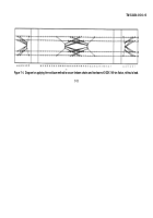
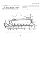
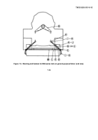
Table 7-7.
Application of Materials for Loading and Securing MO60-Series Tanks on General-Purpose Flatcar
(Figs.
7-5, 7-6, and 7-7)
Item
No.
Required
Application
A
Brake-wheel clearance. Minimum clearance required is 6 in. above, in back of, and on both
sides of, and 4 in. underneath wheel.
B
2
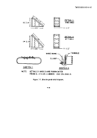
Chock blocks (detail 1, fig 7-7). Place the incline face of the block against the track, even with
the inboard edge at the front of vehicle.
C
2
Chock blocks (detail 2, fig 7-7). Place the incline face of the block against the track, even with
the inboard edge at the rear of vehicle.
D
4
End cleats. Each consists of two pieces of 2- X 12- X 18-in. lumber. Place one against both
items B and C. Secure the lower piece to the floor with four 30d nails and the top piece to the
one below, in a like manner, with four 30d nails.
E
8
Side cleats. Each consists of one piece of 2- X 4- x 24-in. lumber. Place one on each side of
items B and C. Secure to item B or floor with four 20d nails.
F
24
Idler wheel chocking. Each to consist of two pieces of 6- X 6-in. lumber X length-to-suit, cut to
fit contour of idler wheels. Place one piece between inside and outside wheels of each road
wheel assembly.
G
12
Tie cleats, 2- X 4-in. lumber X length-to-suit. Place on top of item F (inside and outside) and
secure with four 20d nails.
H
4
Shackles. Secure one shackle to each towing lug (two at front end of vehicle and two at rear
end).
I
16
Thimbles. Place one thimble at each item H and one thimble under each stake pocket.
J
8
Wire rope, 5/8-in. Attach to each item H and stake pockets (as shown in sketch 2, fig 7-7).
K
48
Clamps, 5/8-in. Secure the ends of each wire rope loop with four clamps. Secure each thimble
with one clamp. (See sketches 1 and 2, fig 7-7.)
L
2
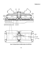
Blocking, inside. Each consists of two pieces of 2- X 4- x 180-in. lumber. Place along the
inside of each track, and nail the lower piece to car floor with sixteen 30d nails evenly spaced.
Nail the top piece to the one below with sixteen 30d nails in like manner.
M
3
Spreaders, inside cleat. Each consists of two pieces of 2- x 4-in. lumber X length-to-suit. Place
one between each end and center of item L. Nail lower piece to car floor with six 30d nails and
nail the top piece to the one below with six 30d nails in like manner.
7-16
Back to Top

